USB and PCI Express
NVIDIA Jetson TX2 NX DG-10141-001_v1.1 | 21
Parameter Requirement Units Notes
Layout recommendations See USB 3.0 Guideline Figure 6-5
Common-mode choke (not recommended – only used if absolutely required for EMI issues).
See Chapter 15 for details on CMC if implemented.
Component Order
Component order Chip AC capacitor (TX only)
common mode choke ESD
Connector: See Figure 6-6.
General: See Chapter 15 for guidelines related to serpentine routing, routing over voids and noise coupling
Notes:
1. Longer trace lengths may be possible if the total trace loss is equal to or better than the target. If the loss is greater, the max
trace lengths will need to be reduced.
2. Recommend trace length matching to <1ps before vias or any discontinuity to minimize common mode conversion.
3. Place GND vias as symmetrically as possible to data pair vias.
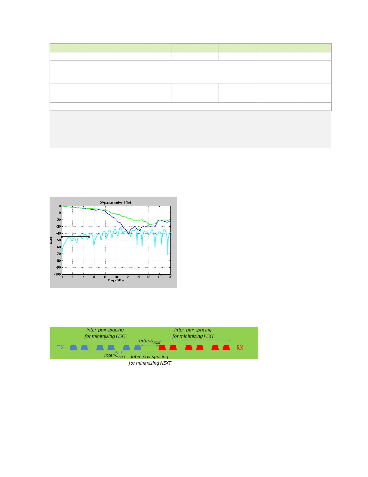
The following figures show the USB 3.0 interface signal routing requirements.
Figure 6-2. IL/NEXT Plot
Figure 6-3. Trace Spacing for TX/RX Non-Interleaving

 Loading...


