43984801TH Rev.1
56 /
Oki Data CONFIDENTIAL
3. Parts replacement
Short plug connector
100/120V Printer : Installation
230V Printer : De-installation rejection
Guide-Cassette-L
Plate-Base-PCB
PCB-Assy
Earth wire
①
❼
⑥
④
②
③
❺
⑥
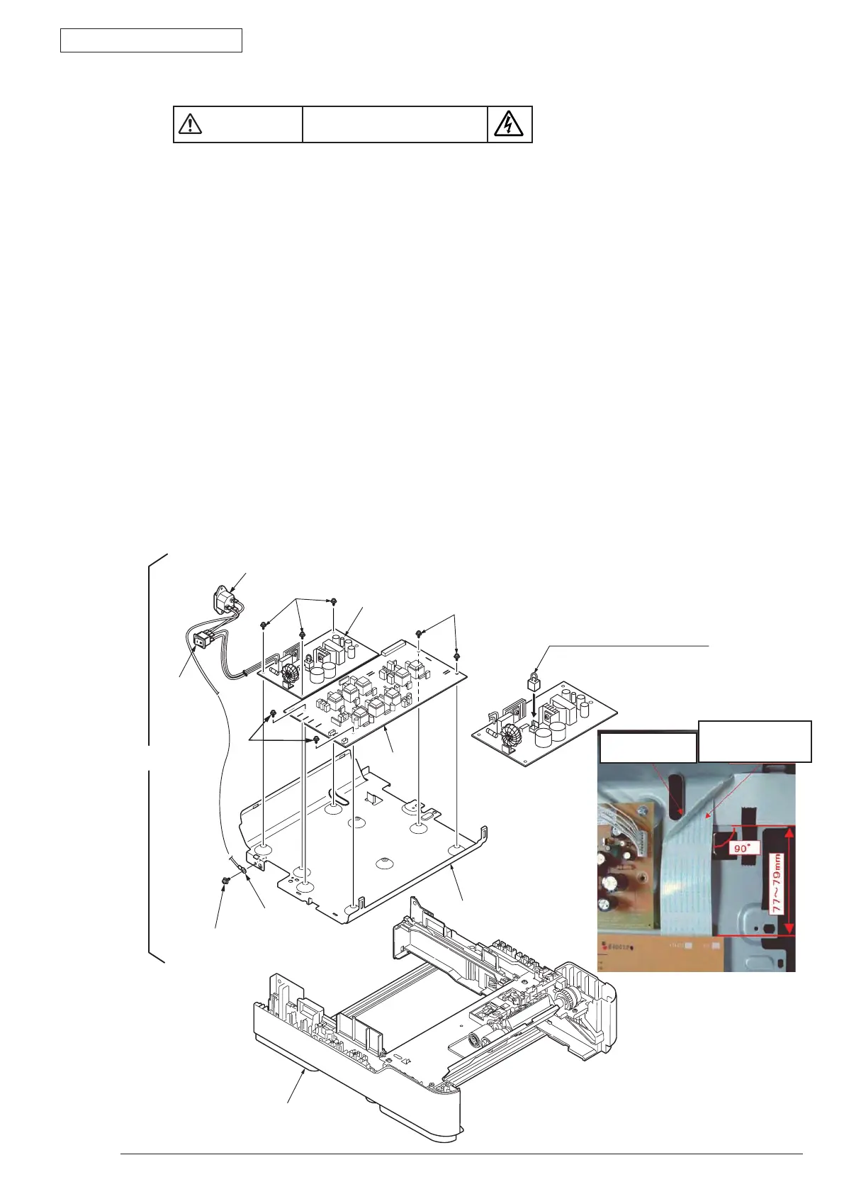
3.3.17 High voltage / Low voltage power board
(1) Open Rear-Cover-Assy.
(2) Open Stacker-Cover-Assy.
(3) Remove Frame-Assy-Lower. (Refer to 3.3.16)
(4) Remove the big screw (Silver)
①
. Remove the earth wire.
(5) R
emove the AC socket
②
and power switch
③
. Remove Guide-Cassette-L.
(6) R
emove the 3 small screws (Silver)
④
. Remove Low voltage power board
❺
.
(7) R
emove the 4 small screws (Silver)
⑥
. Remove High voltage power board
❼
.
(8) I
nstalling is performed by the inverse procedure with removing.
(Note on removing / installing)
1. B
eware of not to touch the DC motor inattentively (Do not rotate motor).
2. Do not apply excessive pressure to the power switch
③
.
3. W
hile installing High voltage / Low voltage power board to the Plate-Base-PCB, do not deform the
Plate-Base-PCB.
Pay attention not
to scratch the FFC.
Pay attention to the
bending direction as
the text printed side up.
Risk of Electric Shock
There is a risk of electric shock during replacement of the low voltage power supply.
Use insulating gloves or avoid direct contact with any conducting part of the power supply, and caution should be
exercised during replacement.
The capacitor may take one minute to complete discharge after the AC cord is unplugged. Also, there is a possibility
that the capacitor doesn’t discharge because of a breakage of the PCB, etc., so remember the possibility of electric
shock to avoid electric shock.
 Loading...