233
Conditions Requiring Routing Tables Section 6-7
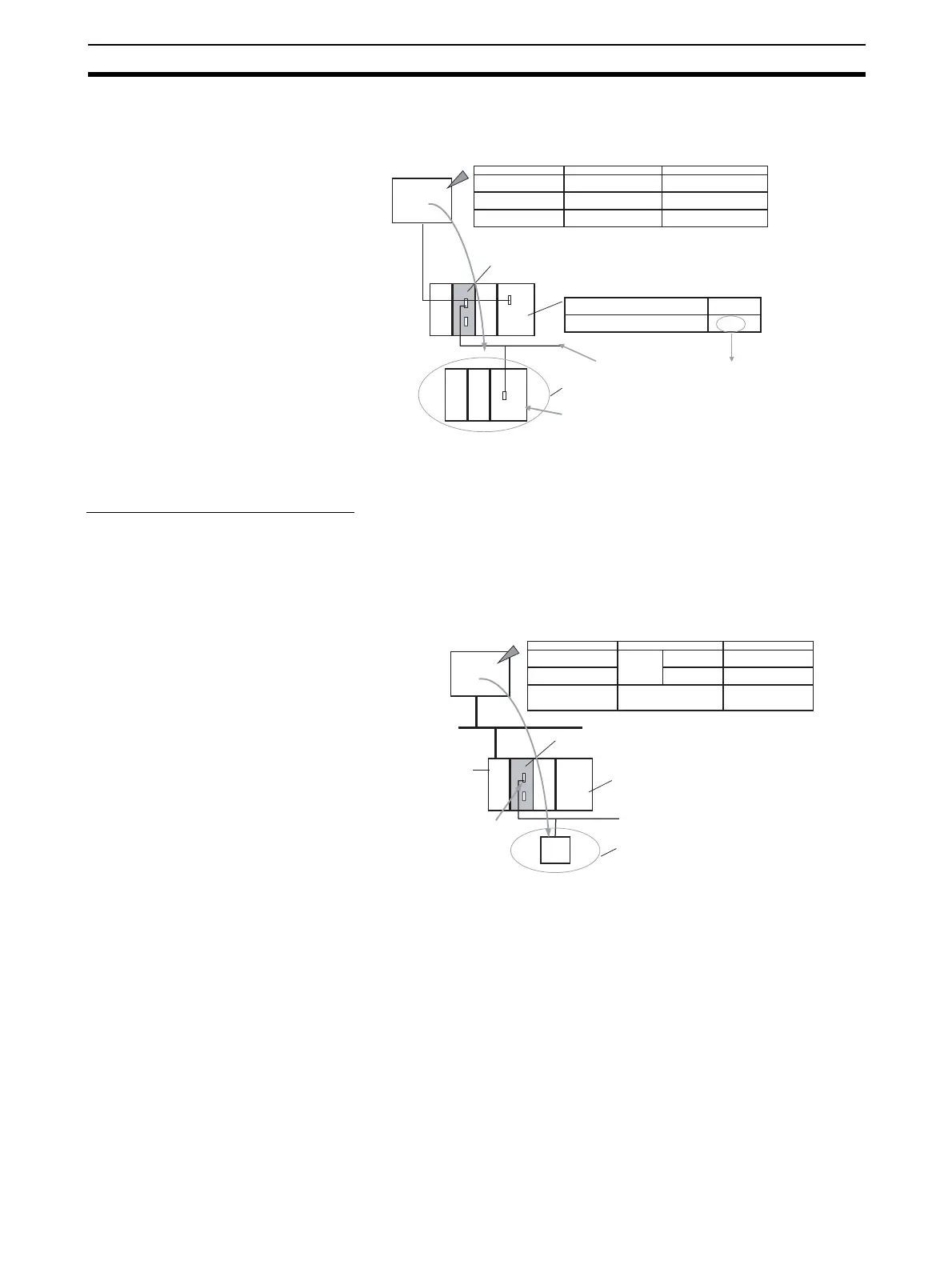
With Routing Tables
Specify the addresses as shown in the following example.
6-7-3 Using a non-PLC Component as the Target
Network-to-Serial Conversion
Routing tables to enable the serial communications path to be treated as a
network are optional.
Without Routing Tables
Specify the addresses as shown in the following example.
Serial Communications Unit/Board
E.g., Unit number 0, port 1
Routing tables for treating serial communications path as a networ
Unit number
80 hex (128 decimal)
Calculated from Unit No. 0, port 1
(1) Network address:
To serial communications path network address A
Target: PLC
(2) Node address: Unit numbers for Host Link (0 to 31) + 1
(3) Unit address: E.g., 00 hex for CPU Unit
A
Address
Contents
Example
PLC
CPU Unit
CPU Unit
Remote network address
Remote node address
Remote unit address
A
s+1
CPU Unit: 00 hex
Address Specification
FINS
command
sent
Serial communications
path (Host Link FINS)
(1) Serial communications path
unit address
(2) Unit No. for Host Link
incremented by 1.
(3) Actual remote unit address
for FINS command
Serial communications
path (Host Link FINS)
Network
address
Serial Communications Unit/Board
E.g., Unit number 0, port 1
Target: OMRON Component or Modbus Slave
Address to distinguish standard PLC
(1) Network address: To N
(2) Node address: To m
FINS network: Network address N
Address Specification
Address
Contents Example
Remote network address
Remote node address
Remote unit address
Serial port unit address
N
m
PLC
CPU Unit
FINS
command
sent
Address to
distinguish
standard PLC
(1) Network
address
(2) Node
address
80 hex (128 decimal)
Calculated from unit
number 0, port 1
FINS Commu-
nications Unit
Serial communications path
(CompoWay/F, Modbus)
Unit address:
To serial port unit
address (e.g., 80 hex)
No routing tables required to treat serial
communications path as a network
 Loading...


