62
Component Names and Functions Section 2-1
2-1 Component Names and Functions
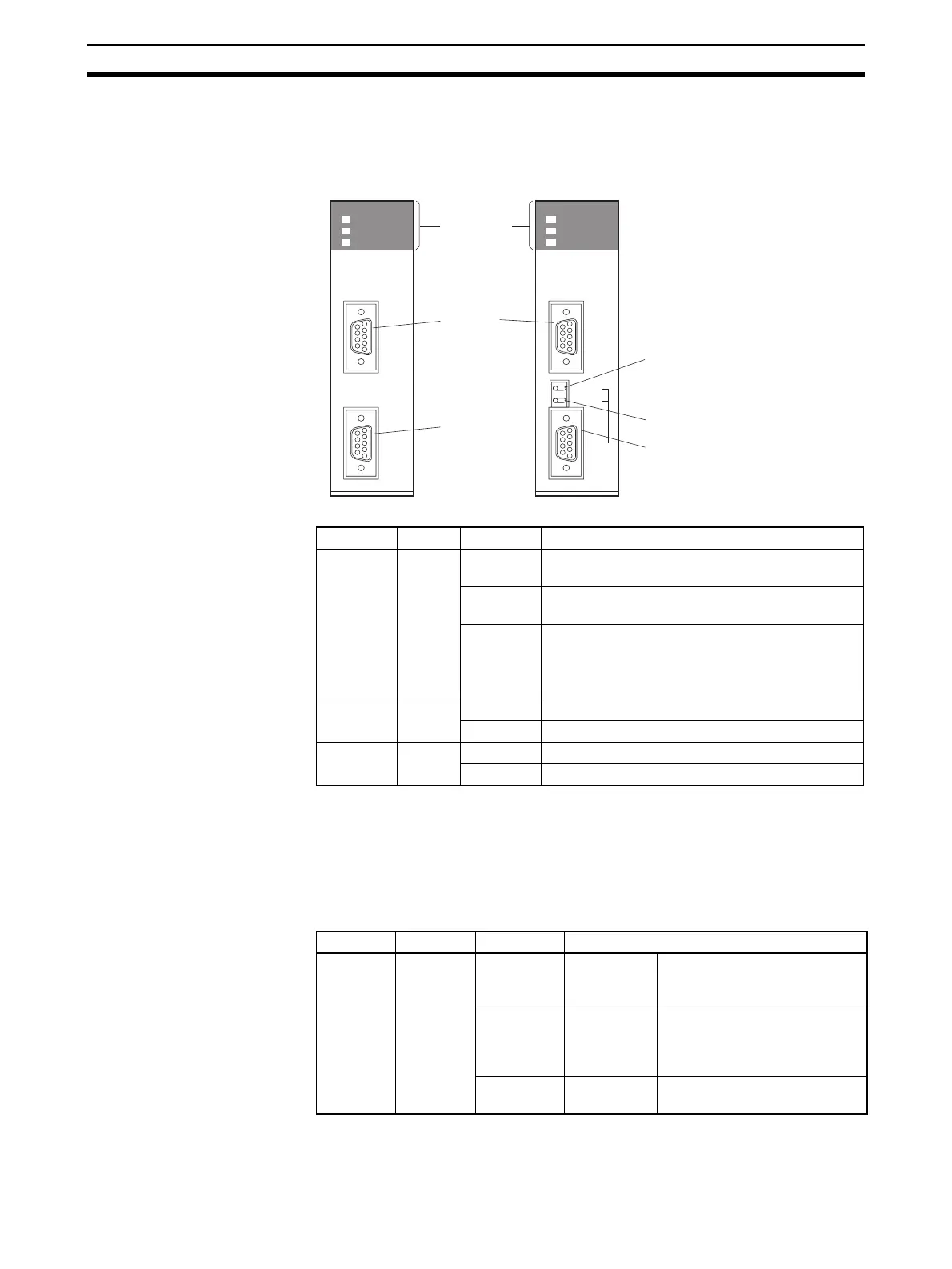
2-1-1 Serial Communications Boards (CS Series Only)
Indicators
Note Depending on the interval of flashing, the meaning is as follows:
Protocol data being initialized: 0.3 s
Protocol data being overwritten: 1.0 s
Protocol data error: 1.0 s and CPU Unit ERR/ALM indicator is flashing
CPU Unit Indicators A Serial Communications Board is mounted as an Inner Board in the CPU
Unit and thus affect the CPU Unit ERR/ALM indicator.
If an error in the Inner Board is the cause of the error indicated on the ERR/
ALM indicator, information on the error will be stored in A424: Inner Board
Indicators
Port 1
RS-232C
Terminating resistance switch
2-wire or 4-wire switch
Port 2
RS-232C
Port 2
RS-422A/485
PORT1
PORT2
RDY
COMM1
COMM2
SCB21-V1
PORT1
ON TERM
4 WIRE
OFF
2
PORT2
(RS422/
RS485)
RDY
COMM1
COMM2
SCB41-V1
CS1W-SCB21-V1
CS1W-SCB41-V1
Indicator Color Status Meaning
RDY Green Lit Operating normally, and protocol macro prepara-
tions have been completed.
Flashing Operating normally, and protocol macros are
being prepared. ()
Not lit An error has occurred in the Serial Communica-
tions Board.
Board/Unit error, CPU Unit watchdog timer error,
Board watchdog timer error
COMM1 Yellow Lit Port 1 is being used for sending or receiving.
Not lit Port 1 is not being used for sending or receiving.
COMM2 Yellow Lit Port 2 is being used for sending or receiving.
Not lit Port 2 is not being used for sending or receiving.
Indicator Color Status Meaning
ERR/ALM Red Lit Fatal error If a fatal error occurs, the CPU
Unit will stop operation in either
RUN or MONITOR mode.
Flashing Non-fatal
error
If a non-fatal error occurs, the
CPU Unit will continue opera-
tion in either RUN or MONITOR
mode.
Not lit Normal
operation
The CPU Unit is operating nor-
mally.
 Loading...


