16
System Configurations Section 1-5
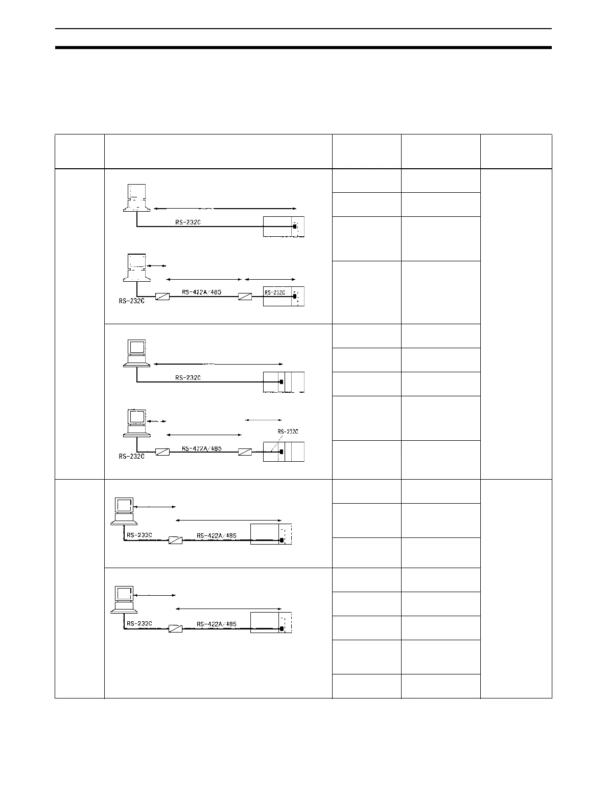
1-5 System Configurations
This section explains the system configuration supported by each serial com-
munications mode.
Host Link Communications
PLC:
Com-
puter
Connection configuration Required
devices
Connected
serial
port/Remarks
Possible com-
mand flow
1:1
Port:
RS-232C
CS1W-SCB21-
V1
Port 1 or 2 Host computer
to PLC:
C-mode or
FINS
commands
PLC to Host
computer:
FINS
commands only
CS1W-SCB41-
V1
Port 1
NT-AL001-E
Converting
Link Adapter
Converts
between
RS-232C and
RS-422A/485
5-V power
supply
For NT-AL001-E
Link Adapter
CS1W-SCU21-
V1
Port 1 or 2
CJ1W-SCU21-
V1
Port 1 or 2
CJ1W-SCU41-
V1
Port 2
NT-AL001-E
Converting
Link Adapter
Converts
between
RS-232C and
RS-422A/485
5-V power
supply
For NT-AL001-E
Link Adapter
1:1
Port:
RS-422A/
485
Connection to Serial Communications Board CS1W-SCB41-
V1
Port 2 Host computer
to PLC
(4-wire only):
C-mode or
FINS
commands
PLC to Host
computer
(4-wire only):
FINS
commands only
NT-AL001-E
Converting
Link Adapter
RS-232C
⇔
RS422A/485
5-V power
supply
For NT-AL001-E
Link Adapter
Connection to Serial Communications Unit CS1W-SCU31-
V1
Port 1 or 2
CJ1W-SCU31-
V1
Port 1 or 2
CJ1W-SCU41-
V1
Port 1
NT-AL001-E
Converting
Link Adapter
RS-232C
⇔
RS422A/485
5-V power
supply
For NT-AL001-E
Link Adapter
Connection to Serial Communications Board.
Note 1.
Resistance ON,
5-V power
Resistance ON
Note 3.
Note 3.
Note 2.
NT-AL001-E NT-AL001-E
Connection to Serial Communications Unit.
Note 1.
Resistance ON,
5-V power
Resistance ON
Note 3.
Note 3.
Note 2.
NT-AL001-E NT-AL001-E
Resistance ON,
5-V power
Resistance ON
Note 3.
Note 2.
NT-AL001-E
Resistance ON,
5-V power
Resistance ON
Note 3.
Note 2.
NT-AL001-E
 Loading...


