278
Auxiliary Area and CIO Area Allocations (Modbus-RTU Slave Mode) Section 9-3
Serial Communications
Mode
Set the serial communications mode to A hex to use Modbus-RTU Slave com-
munications.
Parity and Baud Rate If user settings are specified for the port settings, the parity and baud rate
must be set.
Modbus-RTU Slave
Address
Set the Modbus-RTU slave address to between 1 and 247 (1 and F7 hex).
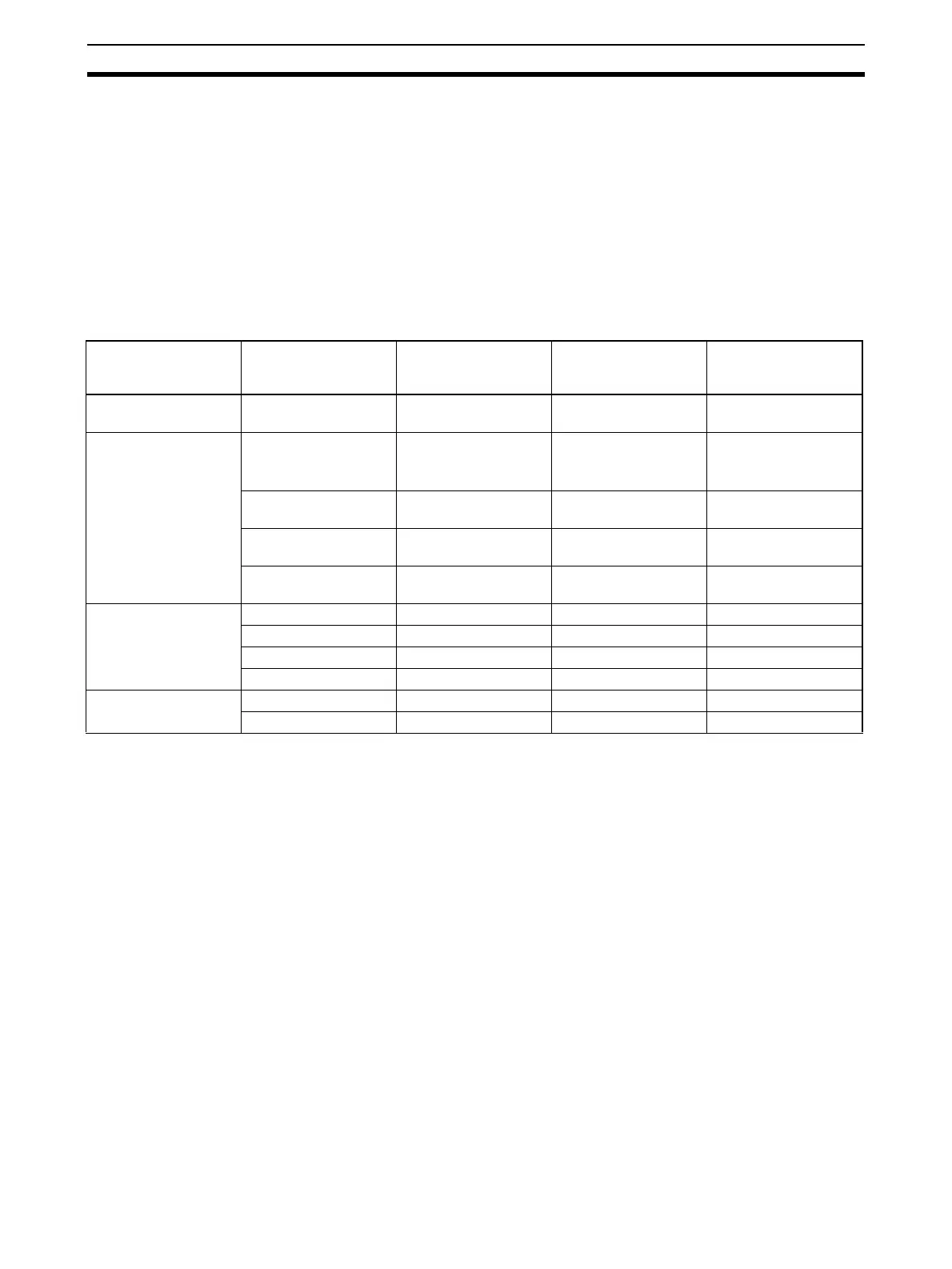
Allocation Areas for Coils, Input Registers, and Holding Registers
The I/O memory areas in the CS/CJ-series CPU Unit that correspond to the
Modbus Data Models (Coils, Input Registers, and Holding Registers) can be
set. The Discrete Inputs data model always accesses the CIO Area.
Note 1. Bits in the following word addresses can be accessed in the CIO Area for
Coils: CIO 0 to CIO 4095
2. An EM bank can be allocated to the Holding Registers by specifying a val-
ue from either 50 to 5C hex or A0 to AC hex (for EM bank 0 to C).
3. Addresses in Modbus data models start from 1, but addresses specified in
Modbus-RTU commands and addresses in the CS/CJ-series CPU Unit
start from 0. Refer to the above table when specifying addresses in appli-
cations.
9-3 Auxiliary Area and CIO Area Allocations (Modbus-RTU
Slave Mode)
This section describes the bits and words used by the Serial Communications
Board and Serial Communications Units in the Auxiliary Area and the Status
Area allocated in the CIO Area. The Software Switches allocated in the CIO
Area are not used for Modbus-RTU Slave communications.
9-3-1 Auxiliary Area Allocations
Port 1 and Port 2 Port
Settings Change Bits
These bits can be turned ON from the program using the OUT or other
instructions to change communications settings and restart the Serial Com-
Modbus data model Modbus address Address specified in
commands
Corresponding CS/
CJ-series CPU Unit
address
Allocation area
setting (in DM Area
settings)
Discrete Inputs 1 to 5120 0 to 5119 CIO 0 to CIO 319
(bits 0 to 5119)
CIO Area (fixed: there
is no setting)
Coils 1 to 65536 0 to 65535 CIO 0 to CIO 4095
(bits 0 to 65535)
(See note.)
CIO Area (default)
1 to 8192 0 to 8191 W0 to W511
(bits 0 to 8191)
Work Area
1 to 8192 0 to 8191 H0 to H511
(bits 0 to 8191)
Holding Area
1 to 15360 0 to 15359 A0 to A959
(bits 0 to 15359)
Auxiliary Area
Input Registers 1 to 6144 0 to 6143 CIO 0 to CIO 6143 CIO Area (default)
1 to 512 0 to 511 W0 to W511 Work Area
1 to 512 0 to 511 H0 to H511 Holding Area
1 to 960 0 to 959 A0 to A959 Auxiliary Area
Holding Registers 1 to 32768 0 to 32767 D0 to D32767 DM Area (default)
1 to 32768 0 to 32767 E@_0 to E@_32767 DM Area bank @
 Loading...


