729
Hayes Modem AT Command Protocol Appendix Q
Modem Settings
When this protocol is used, it is required that the modem connected to the Serial Communications Unit/Board
be initialized to the following conditions:
Note 1. It is recommended that, in addition to the above settings, the abort timer should be set so that com-
munications are cut off if a communications error happened due to incidents such as cable discon-
nection between the Serial Communications Unit/Board and modem. The abort timer is set to 10
minutes for the modem initialization (specialized) (Sequences No. 560, No. 570, No. 580:
Initialize
Modem (Specialized)). Refer to modem’s manual for further information about abort timers.
2. The data format of the modem (baud rate, data length, parity, stop bit) is set by AT commands issued
from a device connected to the modem. Its settings should conform to communications conditions of
the device which issues AT commands. Therefore when communications are made between the mo-
dem and Serial Communications Unit/Board, it is required that communications conditions should be
set by issuing AT commands from the Serial Communications Unit/Board.
3. Modem settings become invalid if the power supply is turned off and must be set again. However, a
memory backup function can be used to protect settings so that even after the power supply to the
modem is turned off, it can communicate with the previous setting conditions.
For Initialize Modem (specialized), the modem initialization command is built in as message data. However, for
Initialize Modem (general-purpose), the command must be specified in the send data for PMCR(260).
Setting Example for Modem Initialization Command
• MD24FB10V Using Sequence #550 (OMRON)
The following command is set in the words specified by the 3rd operand of PMCR(260).
ATE0V0X4\V2\N3%C0*C0\X1&M0S26=10
Note Turn ON pin 4 of DIP switches SW3 on for this Modem (ER signal always ON).
Command echo No
Result code display format Numeric format
Speed display, busy/dialling tone detection at connec-
tion
Baud rate display enabled, busy and dialling tone
detection enabled.
Error correction data compression display Error correction/data compression display enabled
MNP setting Error correction provided (auto-reliable mode)
MNP class setting MNP class 4
V.42 compression, Error correction Not enabled
Flow control between terminal modems Not enabled
ER signal control Always ON
Escape code +
OPR 1 (Communications port settings)
OPR 2 #0226 (Sequence No. 550)
OPR 3 Address for first word containing initialization command character
string S
OPR 4 None (Set #0000)
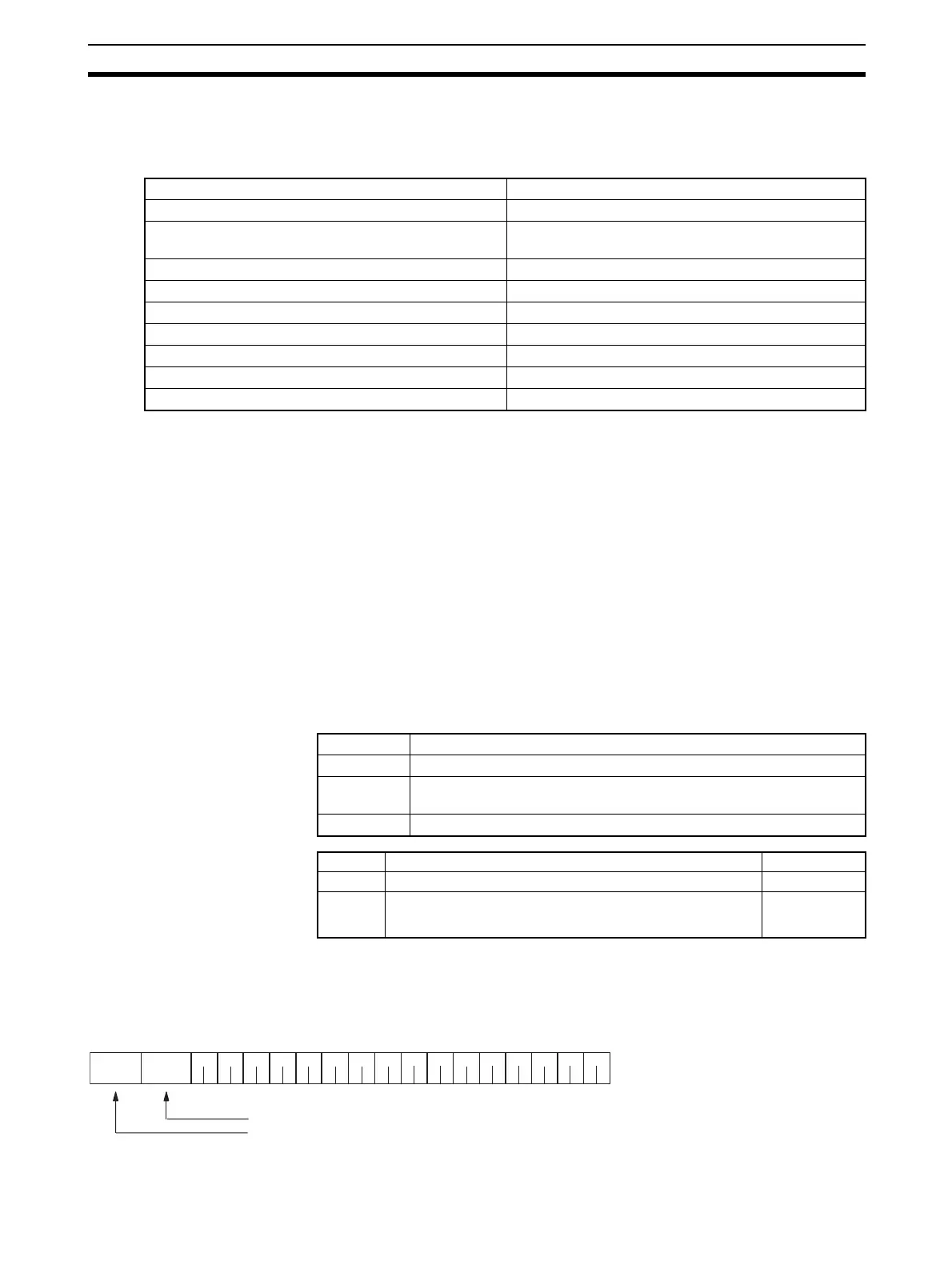
S+0 Number of words from address set for operand 2 to end of data 4 digits Hex
S+1 Number of bytes for send data (initialization command) 4 digits Hex
S+2
:
S+n
Send data (initialization command)
(Fill data to left for odd numbers of bytes)
ASCII
Character string length of modem initialization command (bytes)
Code length of PMCR(260) when it is used (words)
A
TE0V0X4\ V2 \ N 3%C
0
* C 0
\
X
1
&M0
S
2
6
=10
0020
0012
 Loading...


