299
Modbus-RTU Slave Function for Replacing Existing PLCs Section 9-6
Note The differences between the command and response frames for 1:N Modbus-
RTU Slaves and 1:1 Modbus-RTU Slaves is as follows:
1:N Modbus-RTU Slave
• Command Format
• Response Format
1:1 Modbus-RTU Slave
The frame format for a 1:1 Modbus-RTU Slave is the same as that for the 1:N
Modbus-RTU Slave, except the @, Modbus-RTU Slave Unit No., and FCS are
omitted.
• Command Format
• Response Format
9-6-2 Modbus-RTU Slave-compatible Device Selection
Pre-Ver. 1.2 Units
In earlier models, when the host computer program used by the C-series
Modbus-RTU Slave Unit was reused in a CS/CJ-series PLC, data could not
be read normally for some programs due to the differences in Modbus-RTU
Slave specifications.
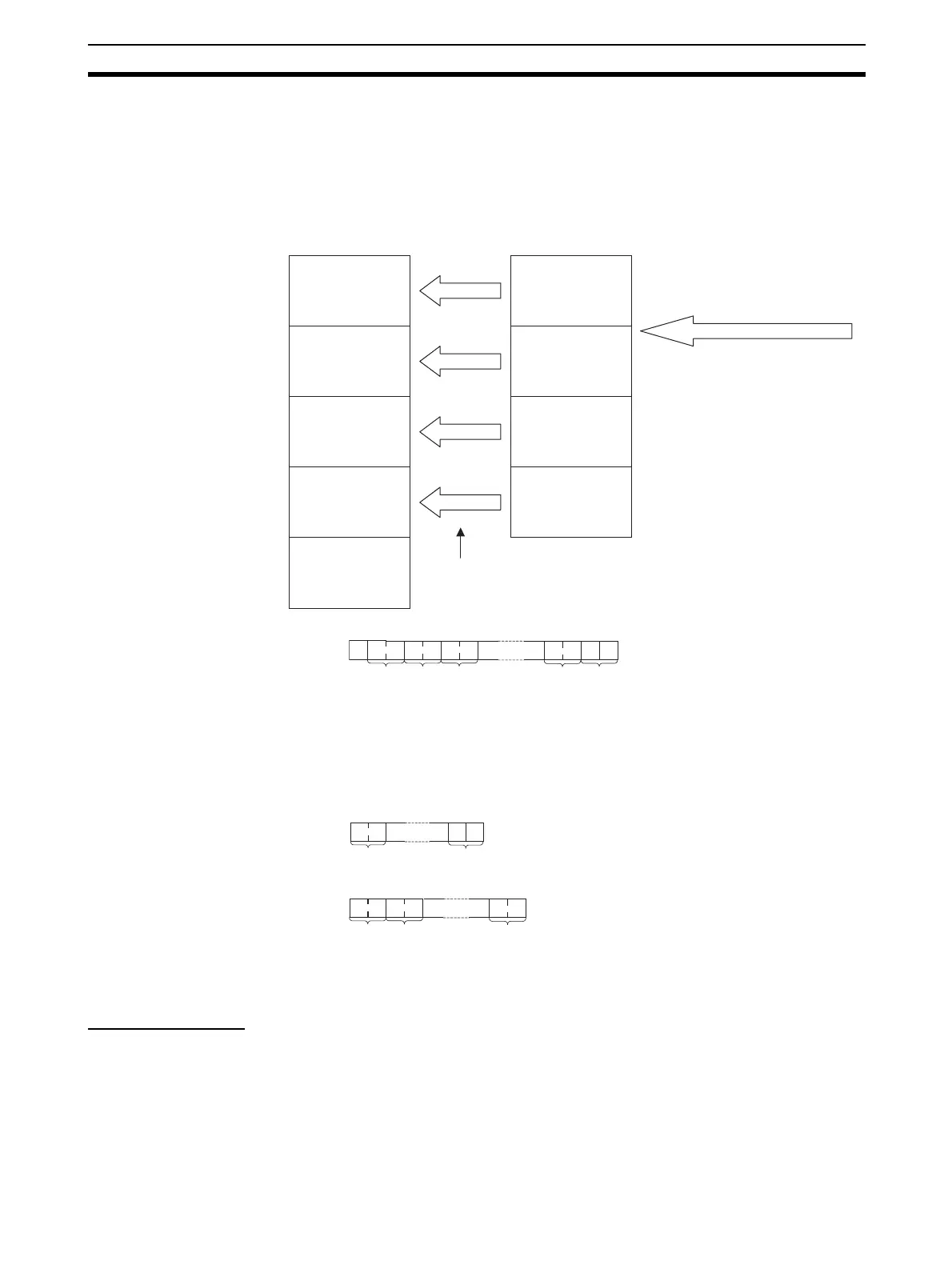
Modbus Data Models
Discrete Inputs
Coils
Input Registers
Holding Registers
1
2
3
:
1
2
3
:
1
2
3
:
1
2
3
:
CIO Area
Work Are
Holding Area
DM Area
0
1
2
:
0
1
2
:
0
1
2
:
0
1
2
:
EM Area
0
1
2
:
Modbus-RTU command
Modbus Commands
Read Coils
Read Discrete Inputs
Read Holding Registers
Read Input Registers
Write Single Coil
Write Single Register
Write Multiple Coils
Write Multiple Registers
DM Area settings are used to
allocate the area for each data
model except for discrete inputs.
I/O Memory
CS/CJ-series CPU Unit
× × * CR
Terminato
FCS
Host Link
Unit No.
Header
code
End
code
@ 0 0 R D 0 0
* CR
Terminato
Header code
R D
* CR
Header
code
End code
R D 0 0
Terminato
 Loading...


