178
Using Protocol Macros Section 5-4
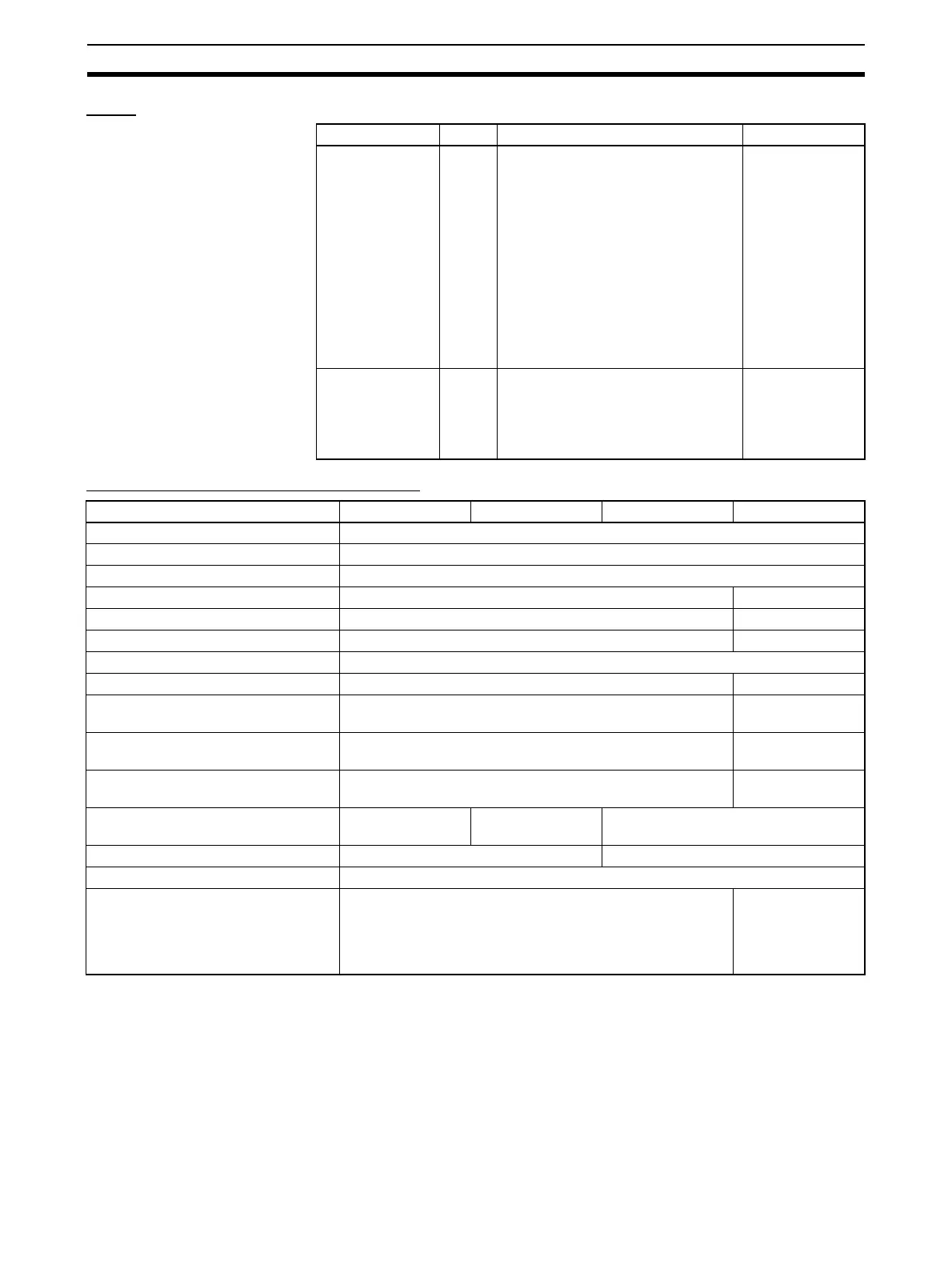
Flags
Operand Areas and Address Ranges
Note The EM Area cannot be specified for the receive data when the interrupt noti-
fication function is being used for a Serial Communications Board. If the EM
Area is specified, a protocol macro syntax error will occur and A42410 will
turn ON.
Name Label ON OFF
Error Flag ER •The Communications Port Enabled
Flag for the specified communica-
tions port (internal logical port) was
OFF when the instruction was exe-
cuted.
• The specified serial port (physical
port) is not set to protocol macro
mode.
• The data setting in C1 is not within
the allowed range.
• The number of words specified in S
or D exceeds 249 (when a word
address was specified for S or D).
All other cases
Access Error Flag AER A read/write-protected area was
specified for send data or receive
data.
A write-protected area was specified
for receive data.
All other cases
Area C1 C2 S R
CIO Area CIO 0000 to CIO 6143
Work Area W000 to W511
Holding Area H000 to H511
Auxiliary Area A000 to A959 A448 to A959
Timer Area T0000 to T4095 ---
Counter Area C0000 to C4095 ---
Data Memory (DM) Area D00000 to D32767
Extended Data Memory (EM) Area E00000 to E32767 (see note)
Extended Data Memory (EM) Area
(including bank specification)
En_00000 to En_32767 (n = 0 to C) (see note)
Indirect DM/EM address, Binary @D00000 to @32767, @E00000 to @E32767,
@En_00000 to @En_32767
(see note)
Indirect DM/EM address, BCD *D00000 to *D32767, *E00000 to *E32767,
*En_00000 to *En_32767
(see note)
Constant Area See Control Data 1
(C1).
0000 to 037E Hex
(0 to 999)
#0000 to FFFF
(Binary data)
Data Registers DR0 to DR15 ---
Index Registers, direct ---
Index Registers, indirect ,IR0 to ,IR15
-2048 to +2047,IR0 to -2048 to +2047,IR15
DR0 to DR15,IR0 to IR15
,IR0+(++) to ,IR15+(++)
,-(- -)IR0 to ,-(- -)IR15
(see note)

 Loading...


