12
2-1 CPU Settings and Parameters
2-1-1 Interface-related Components on CPU
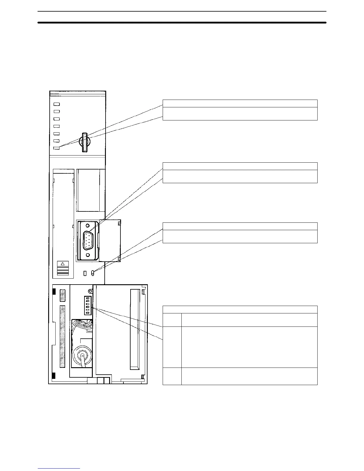
The following illustration shows the various parts of a CV-series CPU that are
related to a Host Link System. Details on the operation of these parts are pro-
vided later in the manual.
HOST LINK
RS-422
RS-232C
COMM (communications) indicator (Orange)
Lit when data is being transferred or received via the host interface.
Host interface port
Connected to RS-232C or RS-422 connector.
Transmission path selector
Set to RS-232C for RS-232C communications.
Set to RS-422 for RS-422 communications.
DIP switch
Pin 6 ON: Connects termination resistance for RS-422.
OFF: Disconnects termination resistance for RS-422.
Pin 4 ON: Sets the following communications parameters:
Baud rate: 9,600 bps
Unit number: 0
Parity: Even
Data length: 7 bits
Stop bits: 2
OFF: Sets communications parameters from the PC Setup.
Pin 3 ON: Enables connection to PT via host link connector.
OFF: Enable connection to host link via host link connector.
(see
note
1)
Note 1. The ON conditions of the communications settings (pin 4) shown above ap-
ply to CPUs with a lot number of “jj75” or greater (manufactured in and
after July 1995.) The settings for those with a lot number of “jj65” or small-
er (manufactured in and before June 1995) are as follows:
Stop Bits: 1
Baud Rate: 2400 bps
CPU Settings and Parameters Section 2-1
 Loading...


