38
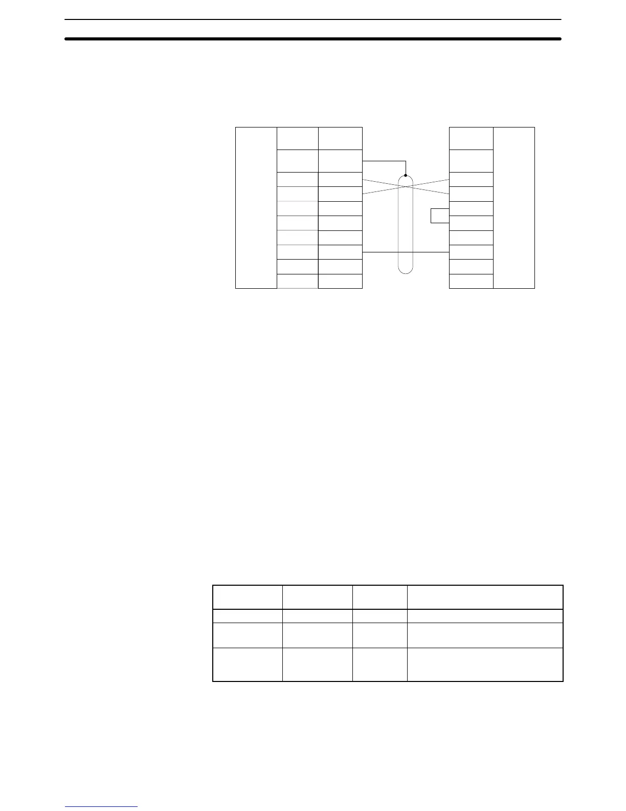
The following diagram shows the connections via communications port 2.
Signal
name
SD (TXD)
RD (RXD)
RS (RTS)
CS (CTS)
SG (GND)
2
3
4
5
9
FG
RS-232C
interface
Pin
number
3
4
5
6
7
8
20
RS-232C
interface
2
Pin
number
Port 2 Host Link Interface Unit
Shield
Connector
hood
1
Note 1. Connect the shield to the connector hood and connector pin 1 of the Host
Link Unit. The other end of the shield must be left unconnected.
2. Turn ON the CTS selector of the Host Link Unit (fixed to 0 V) and specify
full-duplex communications with the CPU Bus Unit System Setup.
3. Refer to Appendix A Standard Models for a list of the PTs that can be used
with the NT600M-LK201 Host Link Interface Unit.
3-7 Optical Interface Connections
The distance between a CPU or Host Link Unit and the host computer connected
to it can be increased to a maximum of 500 m by using an optical interface.
3-7-1 Required Devices
The following devices are required to use an optical interface.
Name Model Required
number
Remarks
Optical Module Z3RN-A-5 2 RS-232C optical fiber conversion
Optical fiber
Z3F2-4DjM
(see note)
1 PCF
AC Adapter Z3-GP01 1 or 2 Two AC Adapters are required for
port 2 and one AC Adapter is
required for port 1.
Note Cables with lengths of 1, 5, 10, 15, 20, 25, 30, 40, 50, 60, 70, 80, 90, 100, 110,
120, 130, 140, 150, 160, 170, 180, 190, 200, 250, 300, 350, 400, 450, and 500 m
are available. When ordering, insert the required cable length before the M in the
model number (replacing the box: j).
Connections via
Communications Port 2
Optical Interface Connections Section 3-7
 Loading...


