28
To connect to a host computer, you will need to prepare a full-duplex or half-du-
plex cable according to the information starting on page 35.
Port 1 supports either RS-232C or RS-422 connections. RS-232C connections
are described in the next subsection and RS-422 connections are described be-
ginning on page 31.
If you are going to use an optical interface via RS-232C, you will need to prepare
a 9-to-25 pin conversion cable according to the information in the section start-
ing on page 38.
To connect to a Programmable Terminal (PT) via RS-232C, you will need to pre-
pare a cable according to the information on page 37. To connect to a host com-
puter, you will need to prepare a full-duplex or half-duplex cable according to the
information on page 35.
3-4 RS-232C Connections
3-4-1 CPU Connections
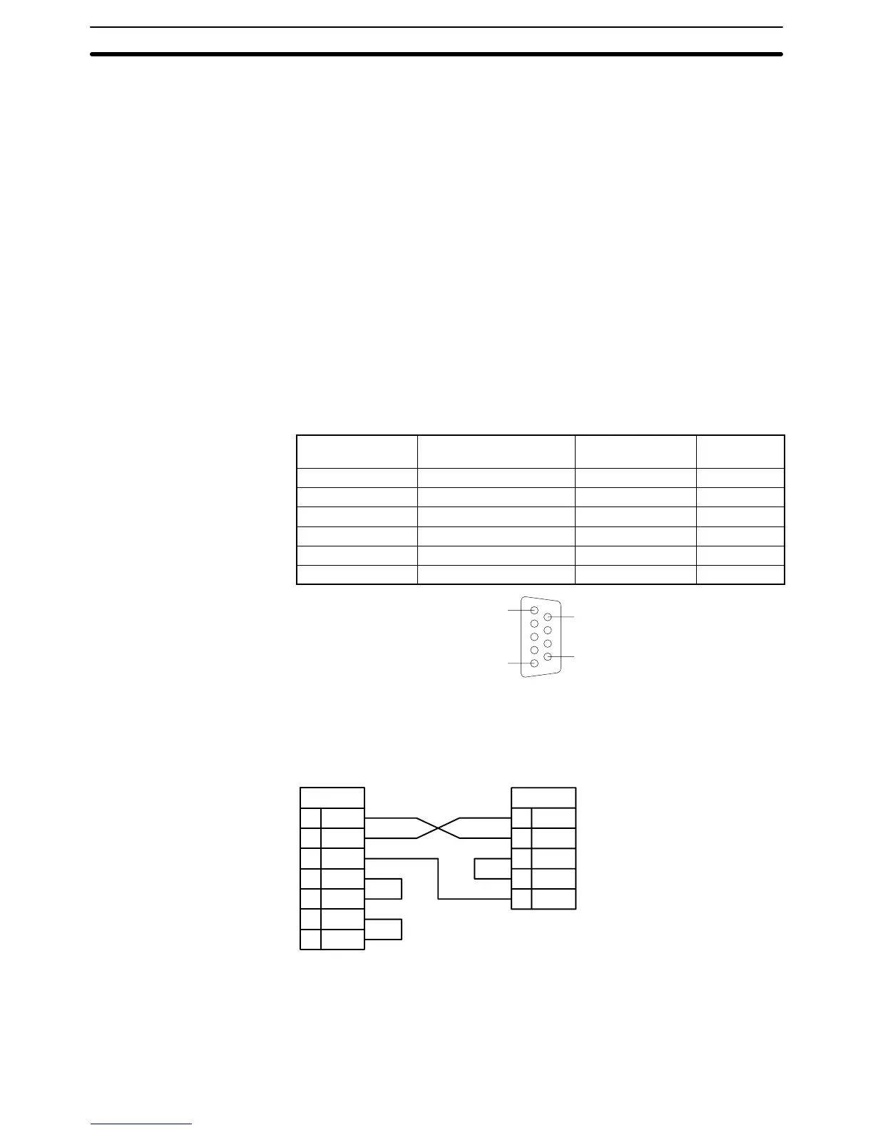
Specifications Electrical characteristics: Conforming to EIA RS-232C
Direction of signal: Viewed from the PC.
Maximum cable length: 15 m
Host interface pin
No.
Signal Symbol Direction of
signal
Connector hood Frame ground FG ---
9 Signal ground SG (GND) ---
2 Send data SD (TXD) Output
3 Receive data RD (RXD) Input
4 Request to send RS (RTS) Output
5 Clear to send CS (CTS) Input
5
1
9
6
Connection Method The following diagram shows the connections between the host computer and
the PC. When RS-232C cable is used, a host computer can be connected to only
one PC.
2SD
3RD
7SG
4RTS
5 CTS
20 DTR
6 DSR
2SD
3RD
4RTS
5 CTS
9SG
Computer PC
Female 25-pin
RS-232C connector
Male 9-pin
Recommended Cable The following cables are recommended for connecting the host computer and
PC. Other cables can be used if desired as long as they meet the required speci-
fications.
Manufactured by Fujikura: UL2464 AWG28 x 5P IFS-RVV-SB (UL approved)
Manufactured by Hitachi: UL2464-SB 5P x AWG28 (UL approved)
Communications Port 2
Connection Cable
RS-232C Connections Section 3-4
 Loading...


