13
2. The cable connecting to the host interface is not available from OMRON.
Refer to Section 3 Installation and prepare an appropriate cable.
3. For setting the termination resistance of the pin 6, refer to Section 3 Installa-
tion.
4. The cable connecting the Optical Interface and the connector on the PC (for
conversion between 25 pins and 9 pins) is not available from OMRON.
2-1-2 Communications Parameters in PC Setup
If pin 4 of the DIP switch on the CPU is turned OFF, the communications parame-
ters for the host interface will be set according to the PC Setup contained in the
CPU. The PC Setup is set from a Peripheral Device, such as the CVSS, and can
be either set offline and then transferred to the CPU or can be set online.
The following parameters can be set. The default setting of each parameter is
shown. These defaults are different from those used if pin 4 is turned ON, i.e.,
you can select either the pin 4 defaults or the defaults listed below to achieve
different settings without specifying them individually. Refer to the CVSS opera-
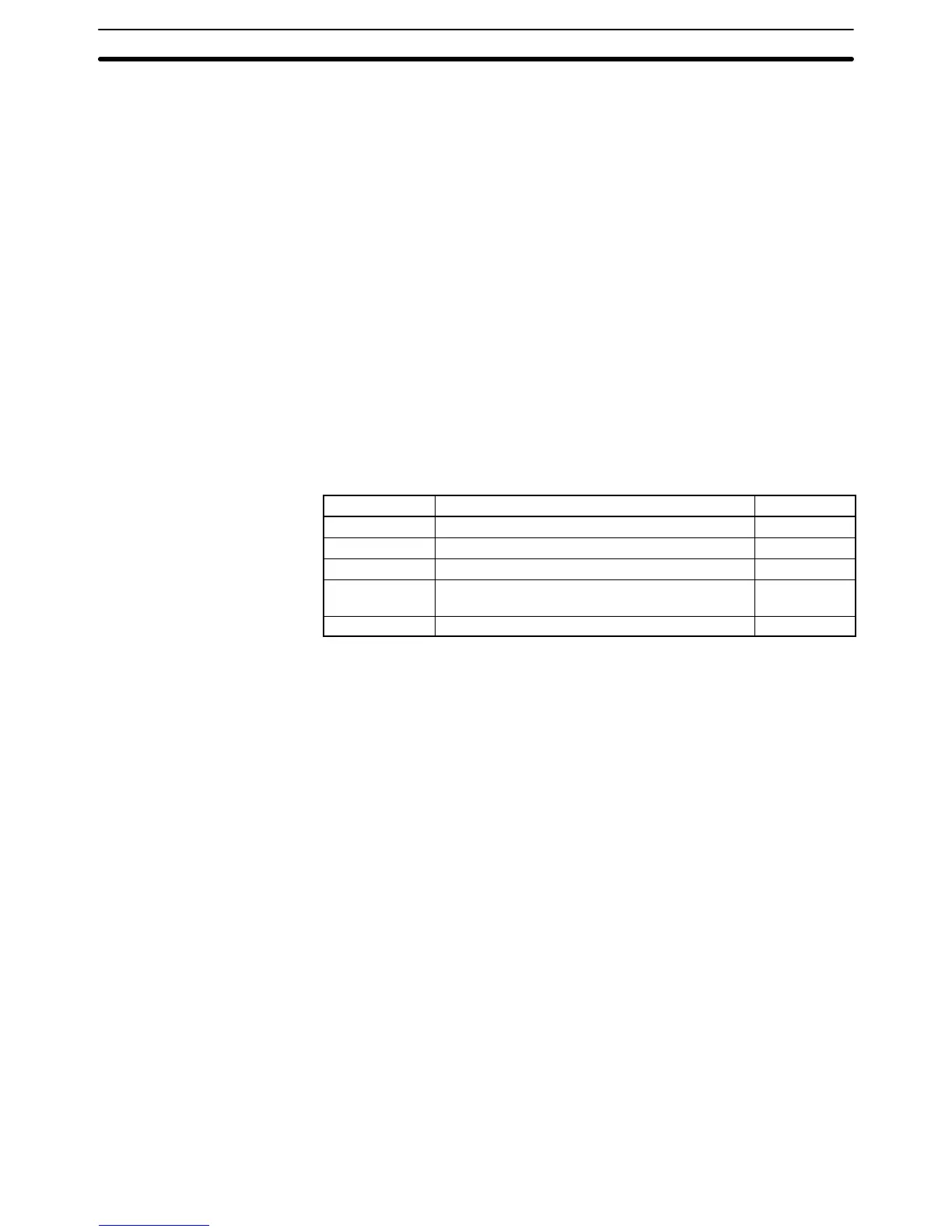
tion manuals for details on changing settings in the PC Setup.
Parameters Possible settings Default
Baud rate 1200, 2400, 4800, 9600, or 19200 bps 9600 bps
Stop bits Either 1 or 2 stop bits 2 stop bits
Parity Even, odd, or no parity Even parity
Data length
(Data bits)
Either 7-bit or 8-bit data 7-bit data
Unit number* 00 to 31 (Used by host computer to identify PCs.) 00
Note *The unit number of the host interface corresponds to the node number of Host
Link Units.
2-2 Host Link Unit Settings and Parameters
2-2-1 Host Link Unit Setting Procedure
Use the following setting procedure for each Unit.
1, 2, 3... 1. Design the system, including the devices to be connected and the connec-
tion methods, referring to Section 1 Introduction.
2. Prepare cables referring to Section 3 Installation.
3. Set Host Link Unit switches referring to 2-2-2 Host Link Unit Setting.
4. Set the CPU Bus Unit System Setup referring to 2-2-3 CPU Bus Unit System
Setup and the CVSS Operation Manual: Online.
5. Connect the system referring to Section 3 Installation.
6. Test communications referring to Section 4 Communications.
7. Operate the system for final checking.
Host Link Unit Settings and Parameters Section 2-2
 Loading...


