33
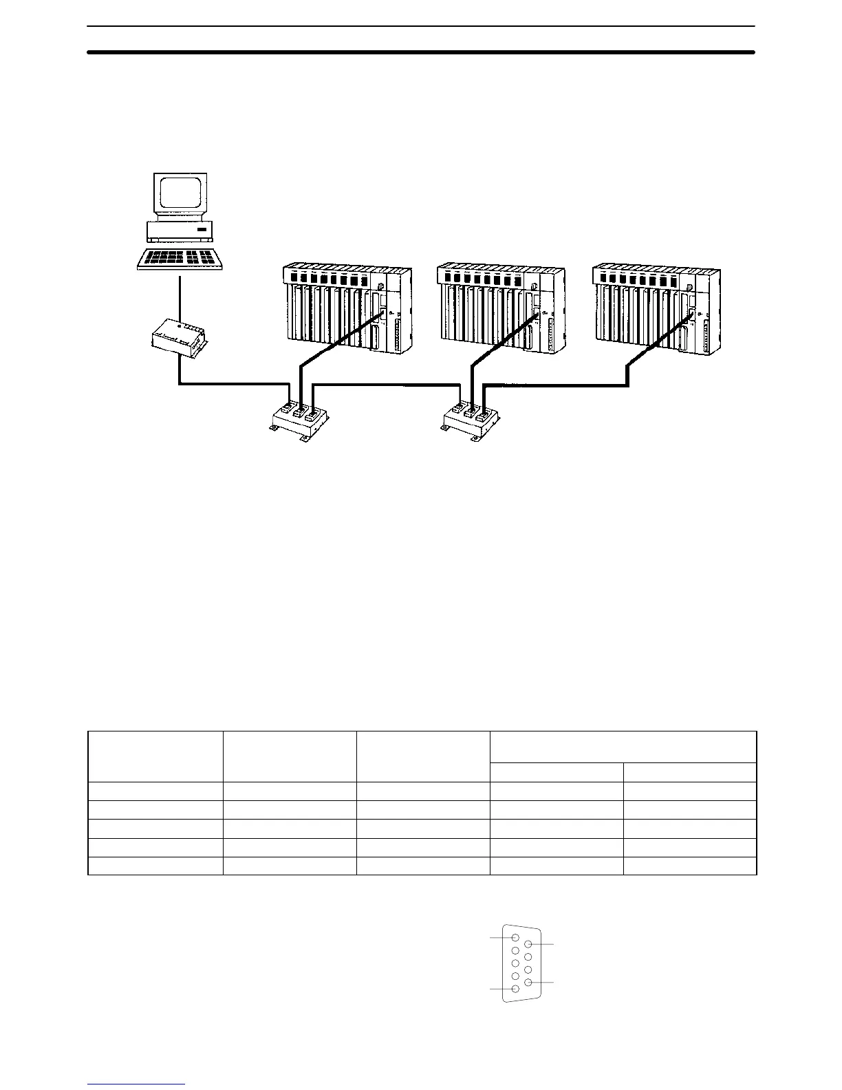
Connect the frame ground to the shield at the connections to the PCs and at
either end of the connections between Link Adapters. An example is shown
below.
Host computer
3G2A9-AL004-(P)E
Link Adapter
RS-232C
(15 m max.)
3G2A9-AL001
Link Adapter
3G2A9-AL001
Link Adapter
Yes: Connect shield to FG.
No: Do not connect shield to FG.
CV-series PC CV-series PC CV-series PC
RS-422
Yes
No
No
Yes
Yes
Yes
No
No No
Yes
RS-422 RS-422
3-5-2 Host Link Unit Connections
The specifications for RS-422 connections to the Host Link Unit are described in
this subsection for port 2. When RS-422 cable is used, a host computer can be
connected to more than one PC.
Communications Port 1 Electrical characteristics: Conforming to EIA RS-232C
Direction of signal: Viewed from the Host Link Unit.
Maximum cable length: 500 m
Host Link Unit
connector pin no.
Signal Symbol Direction of signal
Input Output
Connector hood Frame ground FG --- ---
1 Send data A SDA (SD–) No Yes
2 Send data B SDB (SD+) No Yes
6 Receive data A RDA (RD–) Yes No
8 Receive data B RDB (RD+) Yes No
5
1
9
6
RS-422 Connections Section 3-5
 Loading...


