34
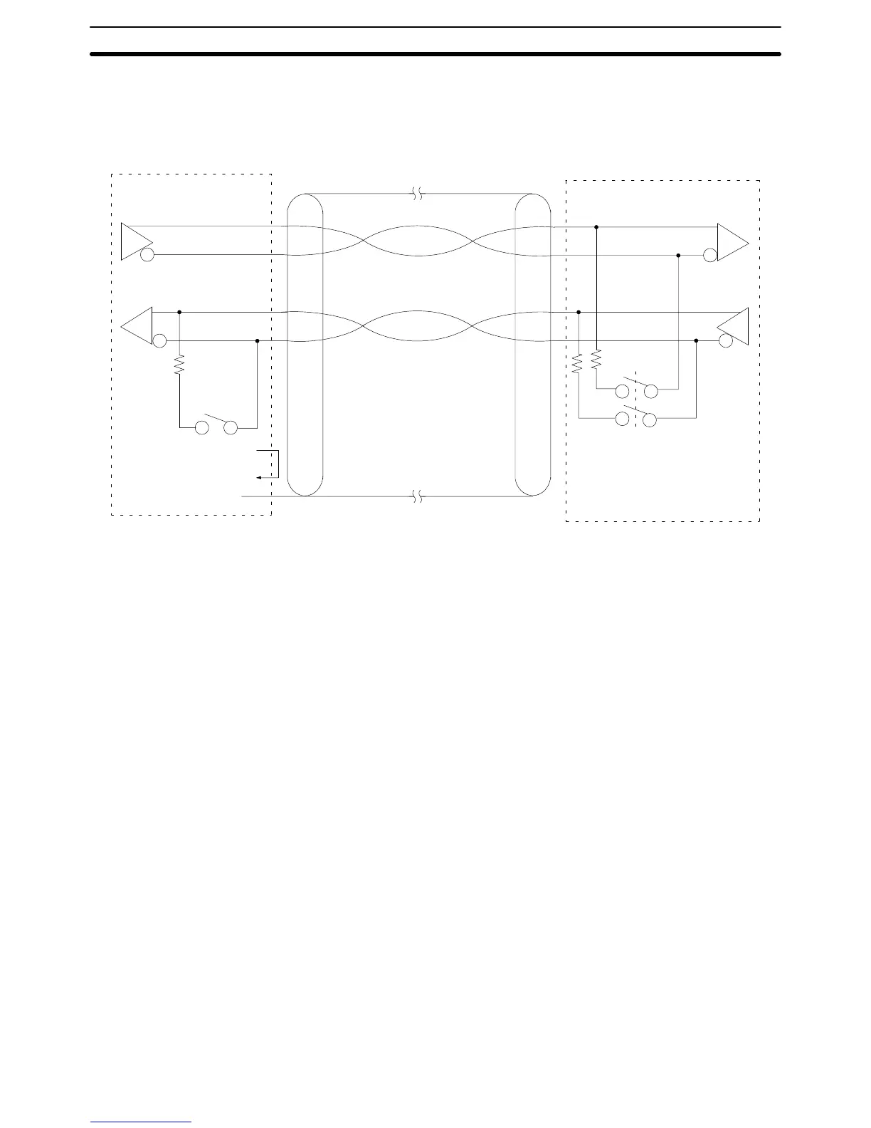
Line Connections The following diagram shows the connections between a Host Link Unit and a
3G2A9-AL004 Link Adapter. When RS-422 cable is used, multiple PCs can be
connected to one host computer by wiring through Link Adapters (see illustra-
tion on page 35).
3G2A9-AL004 Link Adapter
FG (connector hood)
Shield
Host Link Unit
(2)SDB
(1)SDA
(8)RDB
(6)RDA
(4)RS*
(5)CS*
SDB (5)
SDA (9)
RDB (1)
RDA (6)
*The RS and CS terminals
need not be connected as
long as the CTS selector is
turned ON
Note 1. Ground the FG terminals of both the PC and the host computer to a a resis-
tance of 100 Ω or less. For details refer to the CV-series PC Installation
Guide and your host computer manual.
2. The termination resistance must be turned ON at the Units (CPU, Host Link
Unit, Link Adapter) at each end of the communications line and must be
turned OFF at all other Units. Do not connect termination resistances to the
other Units or normal transmission operation will not be possible (refer to 3-8
1-to-N Connection Examples).
3. When connecting the shield to the frame ground, connect it at only one end
of each cable section to prevent current flow (refer to the next subsection
and to 3-9-4 Hood Assembly).
RS-422 Connections Section 3-5
 Loading...


