31
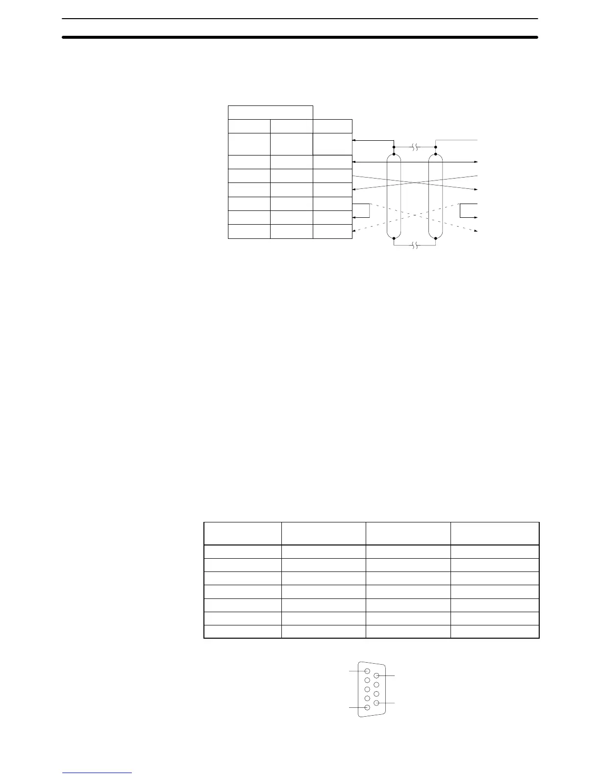
Line Connections The following diagram shows the connections between the host computer and
the Host Link Unit. When RS-232C cable is used, a host computer can be con-
nected to only one PC.
9
2
3
4
5
7
Pin number
9-pin
Host
Link
Unit
Host computer
7
2
3
4
5
8
25-pin
Connector
hood 1
Connector
hood
SG
SD
RD
RS
CS
CD
FG
*1
SG
SD
RD
RS
CS
CD
FG
*2
Shield
Signal
Note 1. It is not necessary to connect these terminals before connecting the host
computer to the Host Link Unit as long as the CTS selector is turned ON.
2. The RS and CD terminals must be connected when connecting the host
computer to the Host Link Unit using half-duplex communications.
3. Ground the FG terminals of both the PC and the host computer to a a resis-
tance of 100 Ω or less. For details refer to the CV-series PC Installation
Guide and your host computer manual.
4. Connect the Host Link Unit to the FG terminal of the host computer via the
shield wire.
3-5 RS-422 Connections
3-5-1 CPU Connections
Specifications Electrical characteristics: Conforming to EIA RS-422
Direction of signal connection: Viewed from the PC.
Maximum cable length: 500 m total
Host interface
pin No.
Signal Symbol Direction of signal
Connector hood Frame ground FG ---
1 Send data A SDA (SD–) Output
2 Send data B SDB (SD+) Output
6 Receive data A RDA (RD–) Input
8 Receive data B RDB (RD+) Input
4 Request to send RS Output
5 Clear to send CS Input
5
1
9
6
RS-422 Connections Section 3-5
 Loading...


