32
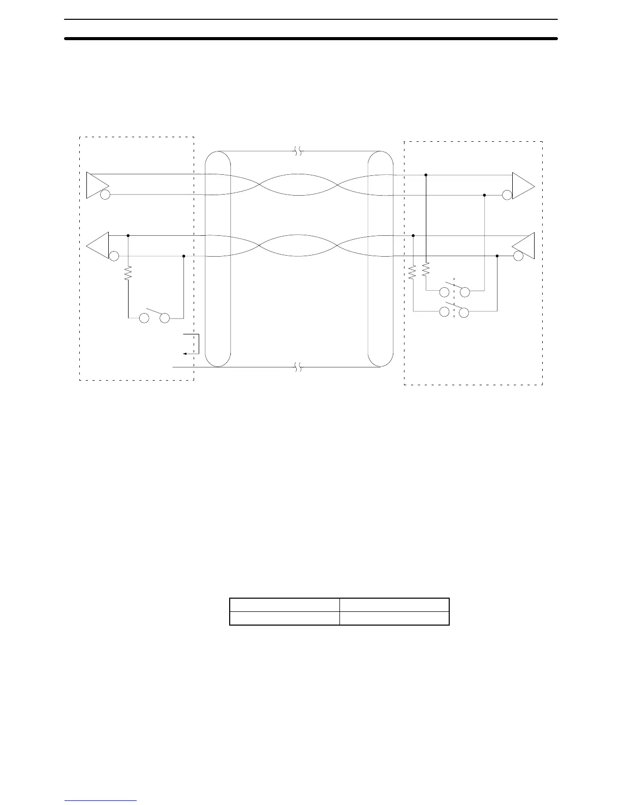
Connection Method The following diagram shows the connections between a host computer and a
3G2A9-AL001 Link Adapter. When RS-422 cable is used, up to 32 PCs can be
connected to one host computer.
3G2A9-AL001 Link Adapter
FG (connector hood)
Shield
CV-series PC
(2)SDB
(1)SDA
(8)RDB
(6)RDA
(4)RS
(5)CS
SDB
SDA
RDB
RDA
Recommended Cable The following cables are recommended for connecting the host computer and
Link Adapter. Other cables can be used if desired as long as they meet the re-
quired specifications.
Manufactured by Fujikura: UL2464 AWG28 x 5P IFS-RVV-SB (UL approved)
Manufactured by Hitachi: UL2464-SB 5P x AWG28 (UL approved)
Note 1. Ground the FG terminals of both the PC and the host computer to a a resis-
tance of 100 Ω or less. For details refer to the CV-series PC Installation
Guide and your host computer manual.
2. The following Connector and Connector Hood (both OMRON) are provided
with the CPU.
Connector XM2A-0901
Connector hood XM2S-0911
3. When using RS-422 cables to connect a Host Link System, the PC at each
end of the communications line must have the built-in termination resistance
connected by turning ON pin 6 of the DIP switch on the CPU. The other PCs
must have termination resistance disconnected by turning this pin OFF. If
termination resistance is not properly set, signal transmission will not be
possible (refer to 3-5 RS-422 Connections).
4. When connecting the shield to the frame ground, connect it at only one end
of each cable section to prevent current flow (refer to 3-1 Preparations).
RS-422 Connections Section 3-5