52
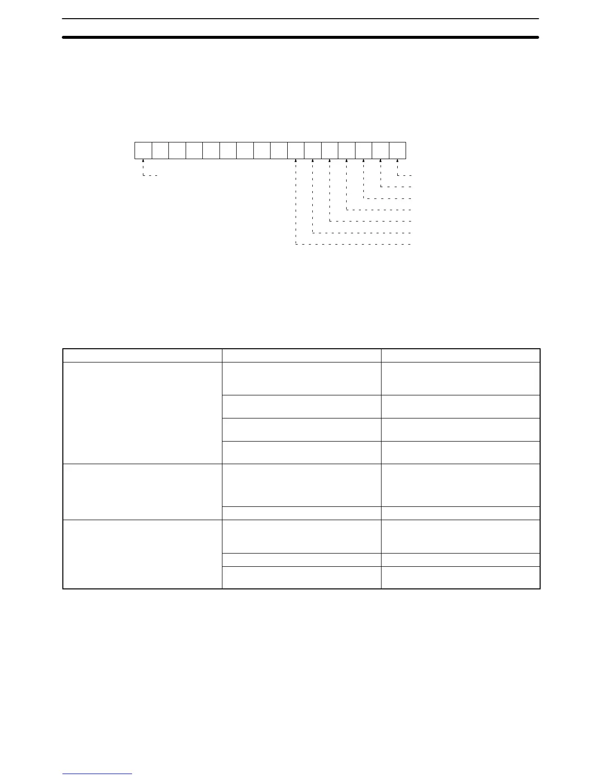
The result of the test for each communications speed is recorded at words 16 to
20 in the portion of the CPU Bus Unit Area allocated to the Host Link Unit in the
PC. The following is an example of the contents of the record at a baud rate of
1,200 bps.
15 14 13 12 11 10 9 8 76543210
00000000
1: Comparison error
1: FCS error
1: Framing error
1: Overrun error
1: Parity error
1: Timeout error
1: CD check error
Word: 1500 + (25 x Unit no.) + 16
Bit
+16
0: Normal response 1: Error
The contents of the following records are
the same as the above.
+17: The result at 2,400 bps
+18: The result at 4,800 bps
+19: The result at 9,600 bps
+20: The result at 19,200 bps
4-2-3 Test Errors and Possible Corrections
When there is an error during the wrap communications test, the cause of the
error can be determined from the Host Link Unit’s indicators. The following table
lists the errors and probable causes of errors that can occur during the wrap
communications test.
Indicator Probable cause Possible correction
RUN indicator is not lit. No power is supplied to the PC or the
voltage of the power supplied to the
PC is low.
Supply power to the PC or increase
the voltage of the power supplied to
the PC.
An error occurred in the Host Link
Unit.
Restart the PC. If an error occurs
again, replace the Host Link Unit.
The Host Link Unit is not properly
secured with screws.
Tighten the screws.
The mounting position of the Host Link
Unit is wrong.
Mount the Host Link Unit to the correct
slot.
TS1 or TS2 indicator flashes and ERH
indicator is lit.
The unit number setting is wrong (the
same number has been assigned to
two or more Units or the number is not
between 0 and 16).
Set the unit number correctly and
restart the PC.
The I/O table is not set correctly. Set the I/O table correctly.
TS1 or TS2 indicator flashes and EC1
or ERC2 indicator is lit.
DIP switch pin 2 or 3 is ON during the
wrap communications test in
RS-232C.
Set DIP switch pin 2 or 3 to OFF and
restart.
The wiring of the connector is wrong. Wire the connector correctly.
Others Check the contents of the CPU Bus
Unit Area.
4-3 C-mode Commands
This section describes the communications method used in C mode. The com-
mands used in C mode and the basic communications method are the same as
those used with the C-series PCs and are the same as the C-mode commands
used with the CPU’s host interface. Details on commands not supported by the
host interface are provided in Section 5 C-mode Commands. Refer to the CV-
series Operation Manual: Host Interface for all other C-mode commands. The
commands and command formats are the same for all other C-mode commands
regardless of whether the host interface or the Host Link Unit is used.
C-mode Commands Section 4-3
 Loading...


