17
2. Each node number must be unique in the same Host Link System.
3. The node number of the Host Link Unit’s communications port 1 is fixed to
00.
4. The node number of the CPU’s host interface is set in the PC Setup. (In the
PC Setup, the node number of the host interface is called the “unit #.”)
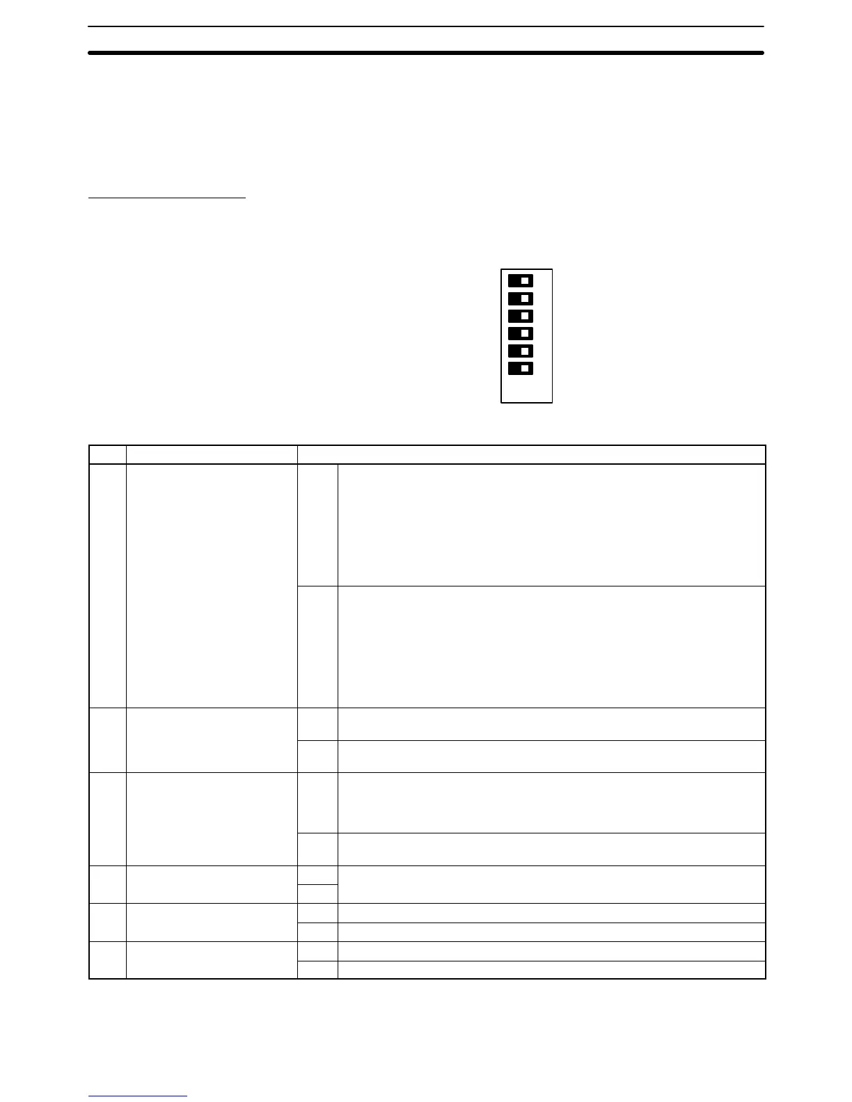
DIP Switch Settings
Pins 1 through 6 on Host Link Unit’s DIP switch are used to control certain com-
munications parameters and tests. These pins are turned ON when they are slid
to the left and turned OFF when they are slid to the right.
ON
6
4
3
2
1
5
OFF
The following settings are possible with the DIP switch.
Pin Function Setting
1 Communications parameters
for communications ports 1
and 2 (see note)
ON Sets the following communications conditions for communications ports 1
and 2.
Baud rate: 9,600 bps
Stop bits: 2
Parity: Even number
Data length: 7 bits
Xon/Xoff control: Not executed
Communications method: Full duplex
OFF Executes the Host Link Unit’s communication using the values in the PC’s
CPU Bus Unit System Setup. The following are default values:
Baud rate: 9,600 bps
Stop bits: 2
Parity: Even number
Data length: 7 bits
Xon/Xoff control: Not executed
Communications method: Full duplex
2 CTS control for
communications port 1
ON Turns ON (sets to 0 V) the CTS signal (clear to send). This pin must be
turned ON if the Host Link Unit is connected to a host computer.
OFF Receives an external signal for CTS. This switch must be turned OFF while
a wrap communications test is being executed.
3 CTS control for
communications port 2
ON Turns ON (sets to 0 V) the CTS signal (possible to receive). This pin must
be turned ON if the Host Link Unit is connected to a host computer via an
RS-232C cable. This pin, however, need not be turned ON if the Host Link
Unit is connected to a host computer via an RS-422 cable.
OFF Receives an external signal for CTS. This switch must be turned OFF while
a wrap communications test is being executed.
4 Not used ON Always turn OFF.
OFF
5 Wrap communications test ON Executes a wrap communications test.
OFF Enables normal Host Link Unit operation.
6 Test port designation ON Designates port 2 for the wrap communications test.
OFF Designates port 1 for the wrap communications test.
Note The ON conditions of the communications settings (pin 1) shown above apply to
CPUs with a lot number of “jj75” or greater (manufactured in and after July
Host Link Unit Settings and Parameters Section 2-2
 Loading...


