61
9. Response monitor time: Set the response monitor time if the response des-
ignation is set to OFF.
The setting range of each control data item is as follows:
Item Range
No. of words transferred 0001 to 0100 (1 to 256 words)
Host Link Unit
communications port no.
00 or 01: Communications port 1
02: Communications port 2
Destination network
address
00: Local network
01 to 7F: Network address (1 to 127)
Destination node number 00: Within local PC
01 to 7E: Node number (1 to 126) (SYSMAC NET)
01 to 3E: Node number (1 to 62) (SYSMAC LINK)
Destination unit address 10 to 1F: Host Link Unit (unit numbers 1 to 15)
Response response 0 (OFF): Response required
1 (ON): No response required
Communications port no. 0 to 7 (0 to 7)
No. of retries 0 to F (0 to 15)
Response monitor time 0000: Default (2 s)
0001 to FFFF (0.1 to 6,553.5 s with 0.1-s increments)
Note In order to execute the SEND(192) instruction properly, it is necessary to pre-
pare a program on the host computer so that the host computer will process the
data that the host computer has received.
RECV(193) Instruction The RECV(193) instruction enables data from the host computer to be written to
the memory areas of the local PC.
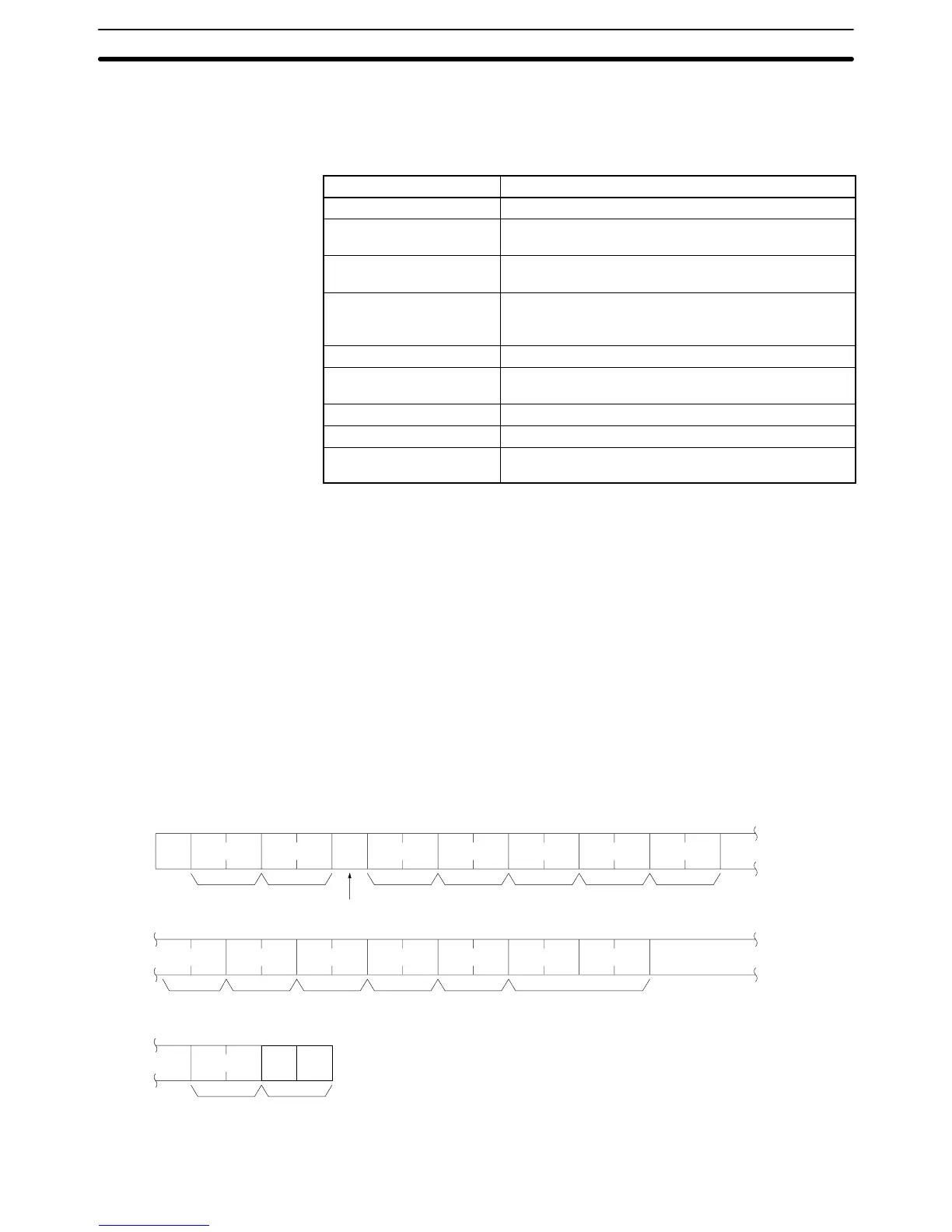
When the RECV(193) instruction is executed, the CV-mode command
“MEMORY AREA READ” (command code 0101) will be sent to the host comput-
er in the following command block format.
@xxOF08x0x0xxxxx
xxxxxxxxxx0101
xx
Node No.
Response delay
Header code ICF RSV GCNT DNA DA1
SNA SA1 SA2 SID Command code
FCS Terminator
DA2
Data
(1,080 characters max.)
*
r
Sending Commands to Host Computers Section 4-4
 Loading...


