Installation
23
ZX2 User’s Manual
INTRODUCTION
BASIC
SETUP
PREPARATION
FOR
MEASUREMENT
TROUBLE-
SHOOTING
INDEX
CONTENTS
SETTING
TRANSITION
CHARTS
FLOW OF
OPERATION
MAIN
APPLICATIONS
& SETTING
METHODS
DETAILED
SETTINGS
SPECIFI-
CATIONS
Height
Double
Sheet
Detection
Positioning
Eccentricity
and Surface
Deflection
Steps
and
Warpage
Thickness
Installation
Before connecting/disconnecting Smart Sensor components, make sure that the power to the
Amplifier Unit is turned OFF. The Smart Sensor may malfunction if components are connected
or removed while the power is ON.
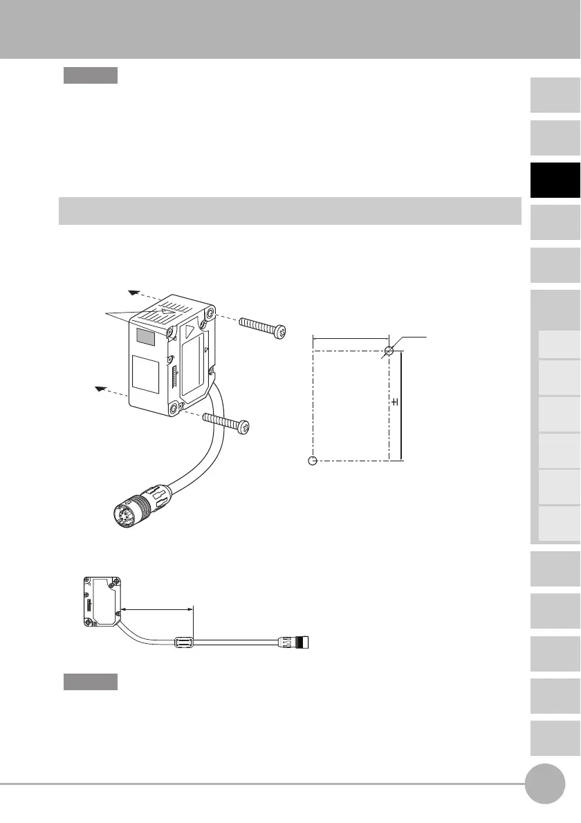
Installing Sensor Heads
Installation Method
• Check the Sensor Head setting position by its emission center mark.
• Fix the sensor head in place with M3 screws. The screws must be tightened with a
torque of 0.5 N•m.
• Be sure to attach the ferrite core accessory on the Sensor Head. Attach it within
100 mm of the Sensor Head side.
• When mounting a Sensor Head, take care not to touch the emitter and receiver. Finger
marks on the emitter and receiver may hinder correct measurements. If you have touched
them by mistake, wipe them with a clean, soft cloth.
• Fix the connectors in places that are not subject to vibration or impact.
Important
27.5
±
0.1
39.5 0.1
2-M3
Mounting dimensional drawing
(unit: mm)
Emission
center position
mark
Within 100 mm
Important

 Loading...