 Loading...
Do you have a question about the Paradox Spectra SP7000 and is the answer not in the manual?
| Partitions | 2 |
|---|---|
| Event Buffer | 256 events |
| StayD Mode | Yes |
| Event Log | 256 events |
| PGM Outputs | 4 programmable outputs |
| Bus | 4-wire communication bus |
| Compatibility | Compatible with Spectra SP Series modules and accessories |
| Communication | Supports IP and GSM communication |
| Wireless Zones | 32 with RTX3 module |
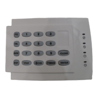
| Keypads | Up to 15 |
| Remote Control | Supports remote control via mobile app |
| Zones | 32 (8 on-board) |
| Battery Backup | 12V 7Ah rechargeable battery |
Details installer, maintenance, and master codes and their functions.
Describes the procedure to access the programming menu.
Explains single digit and feature select programming methods.
Details key mapping for decimal and hexadecimal data input.
Guide to activating and using walk test mode for system checks.
Programming zones, types, and partitions for system zones.
Setting entry/exit delays, bell cut-off, and time/date.
Managing installer, maintenance, and system master codes.
Programming PGM functions, types, and delays.
Worksheet for zone assignments and arming methods.
Zone recognition information for MG control panels with ZX8 modules.
Zone recognition information for SP control panels with ZX8 modules.
How to define zones, their types, partitions, and options.
Assigning wireless transmitters to system zones.
Details on programming programmable outputs (PGMs).
Comprehensive list and descriptions of system events.
Worksheet for programming PGM activation/deactivation events.
Details programming options for PGMs.
Worksheet for recording system access codes.
Instructions for assigning wireless keypads to the panel.
Instructions for programming remote controls.
Detailed worksheet for programming remote controls.
Programming system timing parameters.
Configuration of system partitions.
Lists supported communication features for control panels.
Detailed list of Contact ID report codes.
List of automatic report codes for Contact ID and SIA.
List of automatic report codes for Contact ID and SIA.
Configuring IP and software settings.
How to view and interpret system troubles.
Chart showing product compatibility with control panels.
Diagrams for connecting single zone inputs.
Diagrams for connecting ATZ zones.
PCB layout and wiring diagram for the MG5000 control panel.
PCB layout and wiring diagram for the MG5050/MG5050E control panel.
PCB layout and wiring diagram for the SP4000 control panel.
PCB layout and wiring diagram for the SP5500 control panel.
PCB layout and wiring diagram for the SP6000 control panel.
PCB layout and wiring diagram for the SP65 control panel.
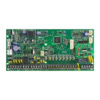
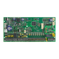
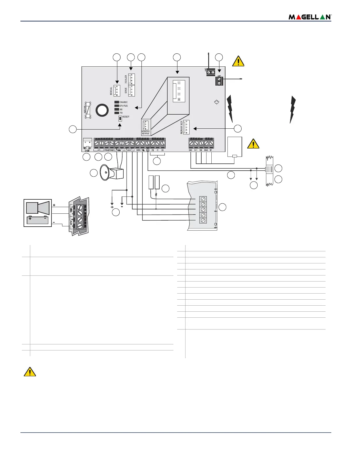
PCB layout and wiring diagram for the SP7000 control panel.
Default settings for EN 50131 compliance.