EasyManuals Logo
Home>Paradox>Security System>Spectra SP7000

Paradox Spectra SP7000 User Manual

Paradox Spectra SP7000
72 pages
To Next Page IconTo Next Page
To Previous Page IconTo Previous Page
Page #64 background imageLoading...
Page #64 background image
Version 4.7/4.92/5.12
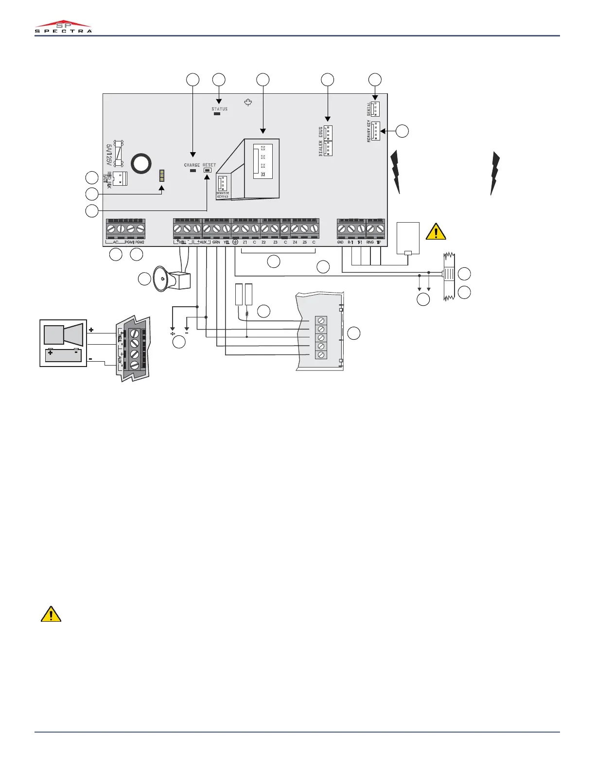
64 | PCB Layouts/Wiring Diagrams
Magellan & Spectra SP • Programming Guide
SP5500
RED BLK
5A/125V
R-1 T-1
RING
TIP
GND
RESET
SERIAL
MEMORY KEY
STATUS
AC
PGM1
PGM2
SERVICE
KEYPAD
SERVICE
KEYPAD
+
AUX
-
GRN YEL
BRN
GRY
RED
GRN
RJ31X
CA 38A
BATT
DIALER
RED BLK GRN YEL
ZONE
Magellan Keypad
1K
EOL
- +
CHARGE
EBUS
AUX
Z2
C
+
-
BELL
+
-
GRN
YEL Z1
Z3 C
Z4
Z5 C
+
_
BELL
+
-
AUX
+
-
TRIGGER
-
+
SELF-CONTAINED
BELL/SIREN
+
-
To provide maximum
lightning protection we
strongly recommend having
separate earth connections
for the dialer and zone
ground terminals.
2
6
12
4 53
Disconnect telephone
line before servicing.
7
8
9
13
14
15
16
17
18
19
20
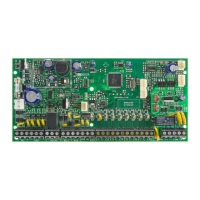
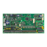
Self-Contained Bell Connection
1
10
11
40 VA transformer strongly recommended.
Max. number of keypads: 15 keypads
Max. aux. current: 700 mA
Max. distance of bus module from panel: 76 m (250 ft.)
Max. total run of wire: 230 m (750 ft.)
This equipment must be installed and maintained by qualified service personnel only.
For UL and C-UL warnings, refer to the UL and C-UL Warnings section at the back of the MGSP Reference & Installation Manual.
The sum of the current drawn from the
BELL and AUX must be limited to 1.3A. Exceeding this limit will overload the panel power supply
and lead to complete system shutdown.

Table of Contents

Questions and Answers:

Question and Answer IconNeed help?

Do you have a question about the Paradox Spectra SP7000 and is the answer not in the manual?

Paradox Spectra SP7000 Specifications

General IconGeneral
BrandParadox
ModelSpectra SP7000
CategorySecurity System
LanguageEnglish

Related product manuals