8
9928492 R04 - 2017-2018 RZR XP 1000 / XP4 1000 Service Manual
© Copyright Polaris Industries Inc.
8.13
14. Install the nut retaining the front stabilizer bar link to
the upper control arm.. Torque fasteners to
specification.
TORQUE
Stabilizer Bar Link Fasteners:
40 ft-lb (54 Nm)
15. Attach shock to A-arm with fastener. Torque lower
shock bolt to specification.
TORQUE
Front Shock Mounting Bolts:
42 ft-lbs (57 Nm)
Lower A-Arm
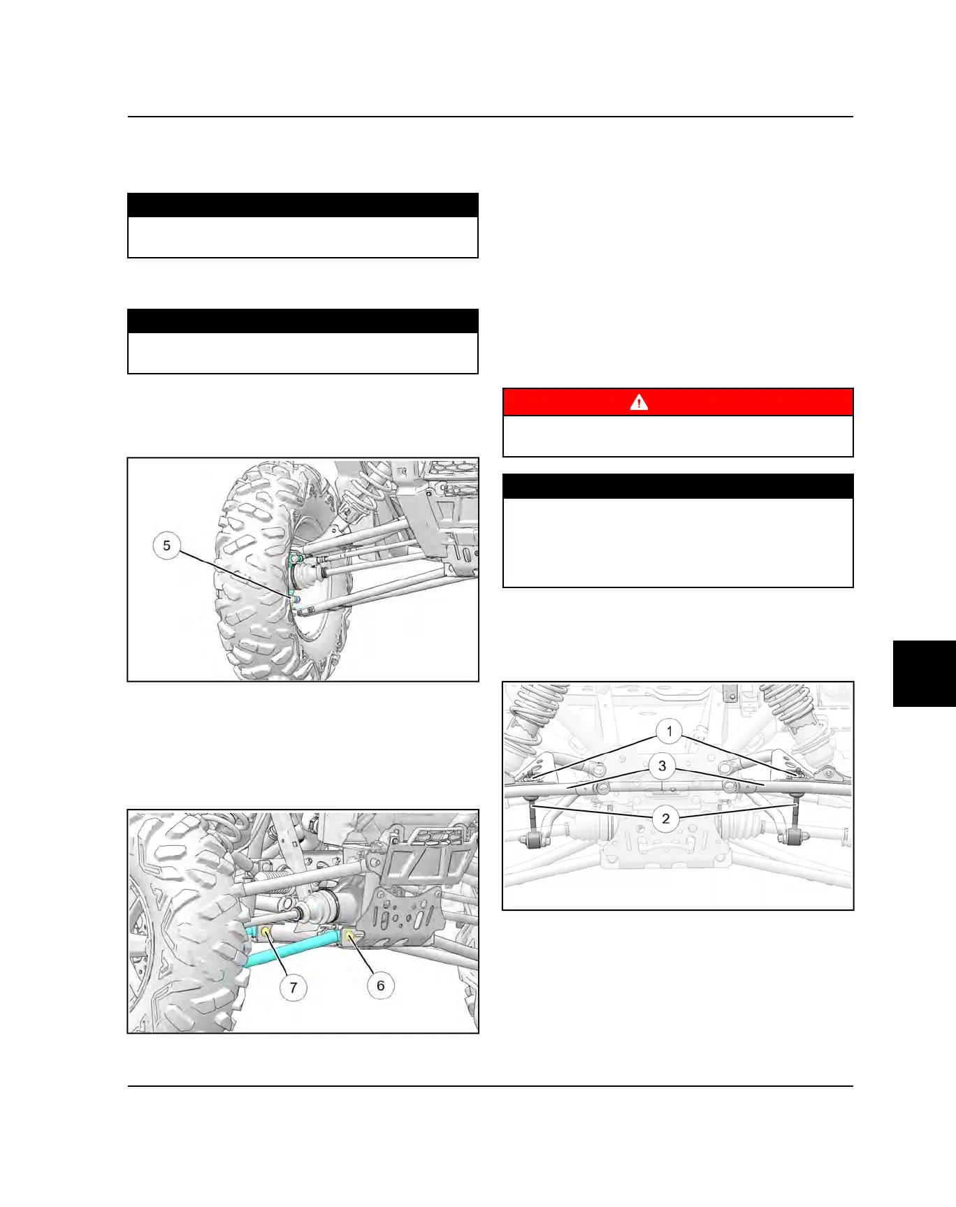
16. Remove lower ball joint pinch bolt
t
from bearing
carrier.
17. Using a soft face hammer, tap on bearing carrier to
loosen the lower A-arm ball joint end while pushing
downward on the lower A-arm. Completely remove
the ball joint end from the bearing carrier.
18. Loosen and remove the lower A-arm front through-
bolt fastener
y
and rear through-bolt fastener
u
.
Remove the lower A-arm from the vehicle.
19. Examine A-arm bushings and pivot tube. Replace if
worn. Discard hardware.
20. If not replacing the A-arm, thoroughly clean the A-
arm and pivot tube.
21. Install new ball joint into A-arm. Refer to “Ball Joint
Replacement” section.
22. Insert new A-arm bushings and pivot tube into new
A-arm. A light press force may be needed.
23. Install new lower A-arm assembly onto vehicle
frame. Torque new bolt to specification.
24. Insert lower A-arm ball joint end into the bearing
carrier. Install lower ball joint pinch bolt into the
bearing carrier and torque bolt to specification.
WARNING
Upon A-arm installation, test vehicle at low speeds
before putting into service.
TORQUE
Lower A-arm Bolts:
42 ft-lb (57 Nm)
Front Ball Joint Pinch Bolts:
42 ft-lbs (57 Nm)
FRONT STABILIZER BAR REMOVAL
1. Remove the nut
q
retaining the front stabilizer bar
link
w
to the upper control arm
e
on both sides.
2. Remove the Fasteners retaining the stabilizer bar
mount to the frame.
3. Remove the stabilizer bar out the side of the vehicle.
STEERING / SUSPENSION
 Loading...