SCALE
WHtn
LINE
/
'-
,~..---
~.--
AX'.
FAONT LENS
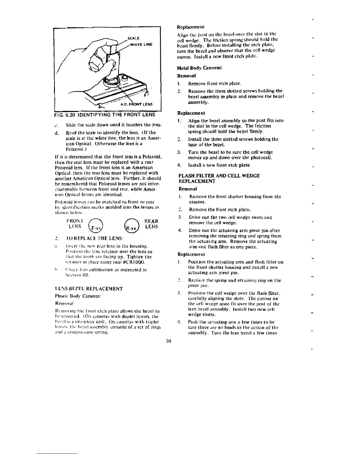
FIG. 5.20
IDENTIFYING
THE FRONT LENS
!..c.
Slide the scale down
until
it
touches
the
lens.
d.
Read
the
SC.lle
to
identify
the
lens.
Of
the
S(:ale
is
at the white line. the lens is an
Amer~
ican Optical. Otherwjse the Jens is a
Polaroid .)
If
it
is
determined that
the
front lens
is
a Polaroid,
then
the
rear
lens must
be
replaced
with
a
rear
Poiaroid lens.
If
the
front
lens
is
an American
Optical. then
the
rear lens must be replaced with
another
Americun
Optical
lens,
Further.
it shQuld
be remembered that Polaroid lenses are
not
inter~
ch.mgeabk
bdween
front
and
rear. while Amer-
iL"an
OpliI..:allense!>
arc identicaJ.
POI;HOid
leo!.cs t'an
be
matched
to
front
or
rear
hy
id"nlific:lIion marks
molded
into
the
lenses as
shown
bl'l\H\ _
FROl'T
REAR
Q n
LEr.;S F-x,
~
LENS
,
TO
REPLACE
THE
LENS,
:J,
l!l\l'n
lhe
MW
r"-;iT
lens in
the
housing.
P""III,Hllh,: !.:m Tl't;Jiner
over
the lens
so
(11.:1
11K'
Il·~'th
<In:
f':h:ing Up.
Tighten
the
h'1.mwr
m
pi,,!.:!,,'
(Ising
100!
#CRI
000.
h
C~h'(f,
kl1'>
collimation
as
instnll;red
in
SlYllon
III.
L["S
BEZEL
REPLACBtENT
Plastic audy
Cameras~
Rt'lllo\-:l1
Rl'!llUnn~·lh<.'
fro111
clt.:h
plat
....
:lllow$
Ihe
bezel
to
lw
h'lIlmct!.
fO;)
t.:;im~ras
with
duple!
lenses.
the
bod
i:-.
,I Ul1.'-Ph:l'I;
unit.
011
t'ameras
wilh
triplet
le:hl'~_
t
1
)<,
ik"ld
'hsl...'mbly eonsiSlS
of
a
set
of
rinl!~
<Jlld.;!
()lmprt'ssion
"pring,
50
Rt."pt3,,-el'itent
Align
thl...'
post
011
tht.·
~l.-eI
over
the
slot
ill
thc
cdl
wetJl-"C',
The
Jriclion
spring
,;hou!tJ hold fhe'
bl.!:tellirmly. Before
instaUin&!
the
clch
plalc~
turn
the
beZ\1'J
and
observe
thaI
th
....
cell
weuge
moves. Jilstall a new front
etch
pl:Jt
l
',
Me
..
1 BodY
u.rn
.....
'
Removal
I.
Remove front etch plate.
1. Remove the three
slotted
screws hoilling
the
bezel
assembly
il\
place
and
remove
the
bezel
<lSSembly.
Replacement
1. Align
the
bezel assembly
so
the post fits
into
tbe
slot
in
the cell wedge.
The
friction
·springshould hold
the
bez.el fmnly_
2,
Install
the
tbree
slotted screws holding the
base
of
the
bez.eL
3.
Turn
the bezel
to
be
sure
the
cell wedge
moves
up
and down
over
the
photocell.
4.
Install a new front
etch
plate,
FLASH
FILTER
AND
CELL
WEDGE
REPLACEMENT
Removal
I. Remove
the
front
shutter
housing from the
camera,
Remove
the
front
etch
plate.
3. Drive
out
the two cell wedge rivets
and
remove the cell wedge,
4. Drive
out
the actuating arm
pivot
pin
after
removing the retaining ring
and
spring
from
tlw actuating arm. Remove the actuating
.Jrm
and
flash filter as
one
piece.
Replacement
I.
Position the actuating ;urn
and
nash filter
on
the front
shutter
housing
and
inst~1I
a new
actuatmg
arm pivot pin.
Replace the sprinp
and
retaining ring on
the
pivol pin.
3,
POSition
the
cell wetlge over the flash
mter.
carefully aligning fhe slors. The
cutout
on
the-
cell wedge must
n(
over
the
post
of
the
lens bezel :.Issembly. Install
two
new cell
wedge ri"ets,
4.
Push
the
actuating
>Inn
a few times
to
be
sure there
,:lfe
no binds
in
the
action
oflhe
assembly.
Turn
the lens bezel
~
few times
 Loading...