-
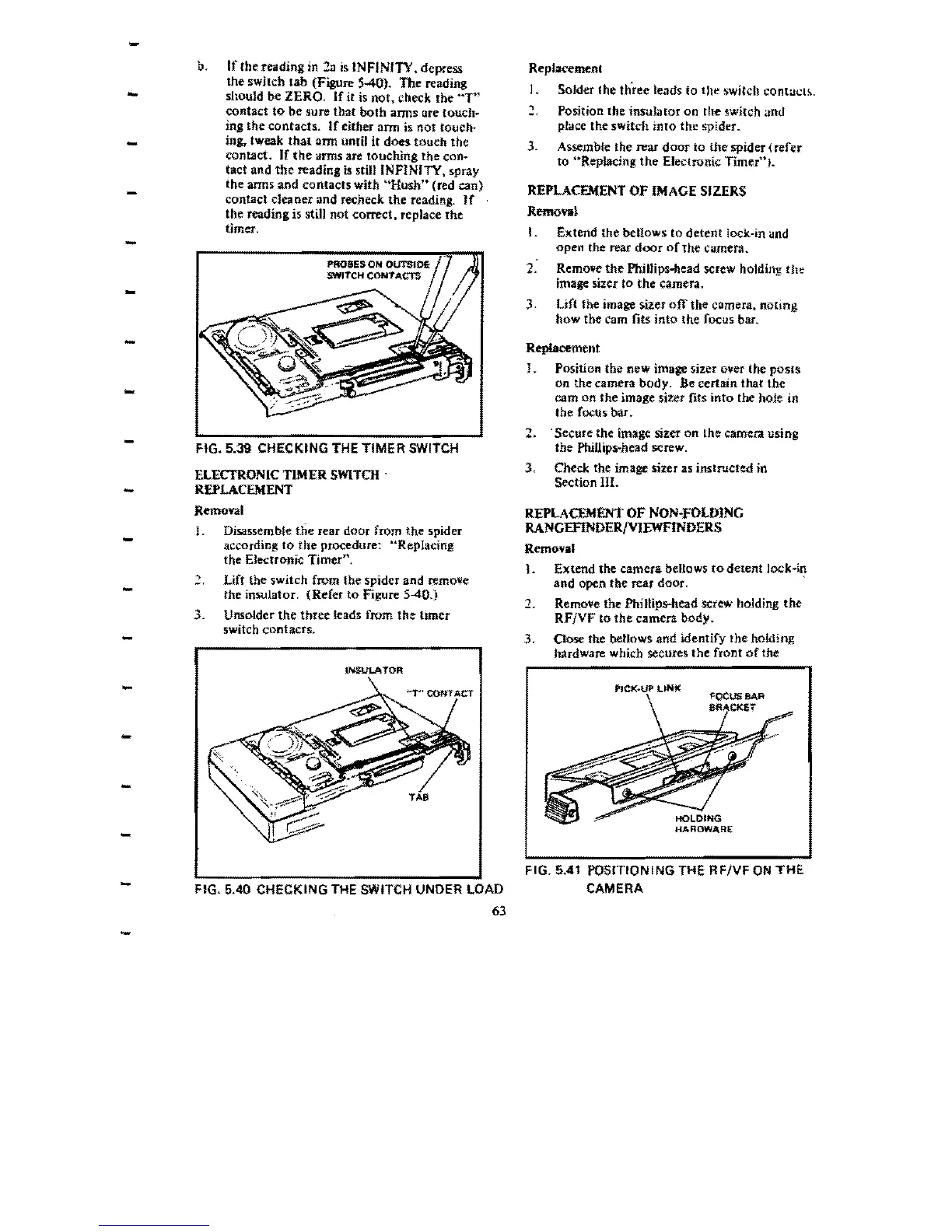
b.
If
the reading in
2n
is
INFINITY. depress
Replacemenl
-
the switch
lab
(Figure
540).
The
reading
I.
SoJder the tllree
le<Jds
to the switch cOnt;Jt.::I!..
should
be
ZERO.
If
jt
is
not.
check rhe
"T"
contact to' be sure that
both
arms are touch.
Position the insulator
on
the switch
and
ing
the contacts.
If
either
ann
is
not
touch~
place the
switch
into
the spider.
-
ing. tweak
that
arm until it does touch the
3.
Assemble the rear
door
10
the
spider
(refer
contact. If
the
arms are touching the
con~
to
··RepiacJng
the
Electronic Timerui.
tact
and
the reading is still INFINITY, spray
the arms
and
contacts
with
"Hush
n
(red
can)
REPLACEMENT
OF
IMAGE
SIZERS
contact cleaner and recheck
the
reading.
If
the reading is still not correct. replace
the
R""",
..
I
timer,
-
I.
Extend the bellows
to
detent
lock-in and
open
the rear
door
of
the
Camera.
2. Remove
the
Phillips-head screw holding
the
image sizer
to
the
camera.
3.
un the image sizer
off
the camera, noting
how
the
Cam
fits into the focus bar.
Replacement
!.
Position the
new
image sizer oller the
posts
on
the
camera body.
Be
certain that
the
cam
on
the
image sizer fits
into
the hoJe in
the focus bar.
-
2. . Secure the image sizer
on
lhe camera using
FIG. 5.39 CHECKING THE
TIMER
SWITCH
the
PhillipS"'head
screw.
3.
Check the image sizer as instructed in
ELECTRONIC
TIMER
SWITCH
.
-
Section
III.
REPLACEMENT
Removal
REPLACEMENT
OF
NON-FOLDING
J.
Disassemble
the
rear door from
the
spider
RANGEFINDERIVIEWFINDERS
- according
to
the procedure: "Replacing
Removal
the Electronic
Timer",
1.
Extend
the
camera
bellows
to
detent
lock-in
,
Lift the switch from the spider and remo\le
-
and
open the rear door. '
the
insulator.
(Refer
to
Figure 5-40.)
1.
Remove the Phillips-head screw holding
the
3.
Unsolder
the
three
leads from
the
timer
RFjVF
to
the
camera
body.
switch contacts.
-
3.
Oose
the bellows
and
identify Ibe holding
hardware which secures
the
front
of
the
INSULATOR
-
-
-
-
-
-
-
-
FIG. 5.40 CHECKING
THE
SWITCH UNDER LOAD
63
-
HARDWARE
FIG. 5.41 POSITIONING THE
RFNF
ON
THE
CAMERA
 Loading...