-
-
-
-
-
-
-
-
-
-
-
-
-
-
-
-
-
handled as follows: Slide
the
focus
baT
to
INFINITY.
Tap
the
new inner frame
(top)
detent
&tide
rivet bole with a
.,
2-56 tap,
Apply Loo-Tile cement sparingly
10
a # 2·56
pan
head
should.ncrew
, A 11336 (avail·
able from Camera Repair.
WaJtham)
and use
the screw
to
secure
the
slide
and
inner frame
(top).
Replace the
RF/VF
if
it
was removed.
3,
Pivot
the
focus
bar
back
jnto
position jn
the
body.
Replace
the
two
focus
bar
rivets and
hardware using
tool
#169454.
BE
SURE
THE
RF
CAM
IS NOT
POSITIONED
BE·
HIND
THE
FOCUS
BAR
BRACKET.
4.
Apply
Loc~Tlle
cement
sparingly
to
the
detent
stud and secure rhe inner frame
(top)
to
the
shutter
shaft.
S.
Position the
detent
on
the
detent
stud so
that
the
notched side
is
toward the lem.
Hand press
in
place.
6. Insert a new spacer between
the
top
inner
frame and the U-frame and install
the
link
pivot using tool #1
J220.
Work
the
focus
bar a few times
to
be sure that
the
linkage
does not bind.
7, Perform the applicable RFIVF
and
lens
checks described
in
Section
ill.
INNER FRAME (BOTTOM)
REPLACEMENT
RnnaYal
1"
Extend
the
bellows
to
detent
lock·in.
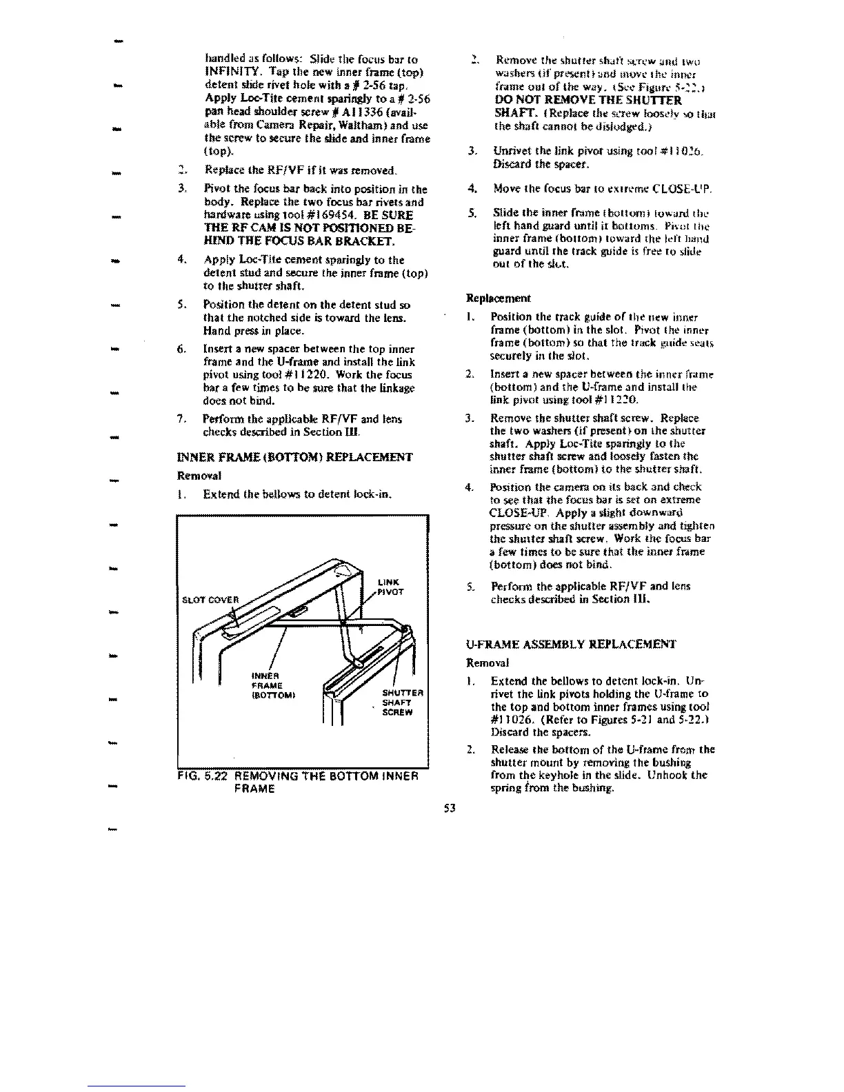
SHUTTER
SHAFT
SCREW
FIG, 5,22 REMOVING THE BOTTOM INNER
FRAME
,
Remove
the
~hutr~r
shan
:;crl.·w
and
lWu
washt!r5 {if present t and
mow
Ihl..'
illn~r
fr.lme
out
of
the way. (St.'\."
Figun'
:;:.~:.)
00
NOT
REMOVE
THE SIlUTTER
SHAFT. {Replace
th~
St.'rew
loosdy
'>0
that
{he shaft
cannot
be dislodged.)
3,
Unrivet
the
link pivot using rool #110';:6.
f.>iscard
the spacer.
4.
Move
the
focus bar
10
eXlrert\e
CLOSE-lIP.
5,
Slide
the
inner frome
Ibotlomi
!OWiJro the
left
hand
guard until it bottoms.
Plmt
th~
inner frame
(bottom
I towurd
the
kft
hiiml
guard untH the track guide
is
free
to
sHue
out
of
the sh
.•
t.
Replacement
I.
Position the track guide
of
the
new
inner
frame
(bottom)
in
the
slot. Pivot Ihe inner
frame
(bottom)
~o
that
the
track guide
sealS
securely in the slot.
2.
Insert a new spacer between
the
inner
rrame
(bottom)
and
the
V-frame
and
installlhe
link pivot using tool
#112~O.
3. Remove
the
shutter
shaft screw. Replace
the
two
washers
(if
present)
on
lhe shutter
shaft. Apply
Loc~Tite
sparingiy
to
the
shutter
shaft screw and loosely fasten the
inner frame
(bottom)
to
the
shutrershaft,
4. Position
the
camera
on
its back
and
check
to
see
that
the
focus bar is set
on
extreme
CLOSE·UP,
Apply.
slight
downward
pressure
on
the
shuuer
assembly
and
tighten
the
shutter
shaft screw. Work
the
focus bar
a
few
times
to
be sure that
the
inner frome
(bottom)
does
not
bind.
S.
Perfonn
the applicable
RF/YF
and
(ens
checks described
in
Section
111.
U·FRAME
ASSEMBLY
REPLACEMENT
Removal
I, Extend
the bellows
to
detent
lock~jn,
Un~
rivet the link pivots holding the
U~frame
to
the
top
and
bottom
inner frames using
toot
#11026,
(Refer to Figures 5·21 and 5·22,)
Discard the
spacers.
2.
ReJease
the bottom
of
the
V-frame from the
shutter
mount by removing
the
bushing
from
the
keyhole
in
the slldt!. Unhook
the
spring from the bushing.
53
 Loading...