-
J. Carefuny spread the
mounting
brdd::ets
al,arl.
Spread
them
just
enough
to
disen--
-
g.age
the optics
OI5Sembly.
Lift out the
assembly.
4.
EXOImine
the viewfinder window.
If
it
is
scratched or
broken.
replace it.
First
remove
-
and
then
clean
out
all glass
with
a low pres-
sure air
hose.
Spread Dupont Duco cement
(or
equivalent) sparingly around
the
window
-
frame
and
gently press the window
into
place. Immediately
wipe
away
any
excess
cement and
thoroughly
dean
the window
-
before
instaUing
the
new optics assembly_
Replacement
-
1,
Squeeze the
mounting
brackets together
untillhey
art
about
the
same distance
apart
as
tbey
were before
the
optics
assembly was
removed,
-
Snap
the optics assembly
into
position
be~
tween the
mounting
brm::kets.
Be
sure
the
-
adjusting screw
is
facing
the
back
of
the
camera.
-
-
-
-
-
-
-
-
-
-
3. Hook
the
~pring
b'JI.:k
in
pla\."<:
Hil
the
oplk~
a:.st:mbly tab.
4, Replace
the
rear window place
ant.!
!IIl'CUft..'
It
with the 1wo retaining SCTI!W:".
5. Perform the applicabte RF,:VF
~hccks
described in Section III.
REPLACEMENT
OF
FliLDING
RF
!VF
MAGNETS
Removal
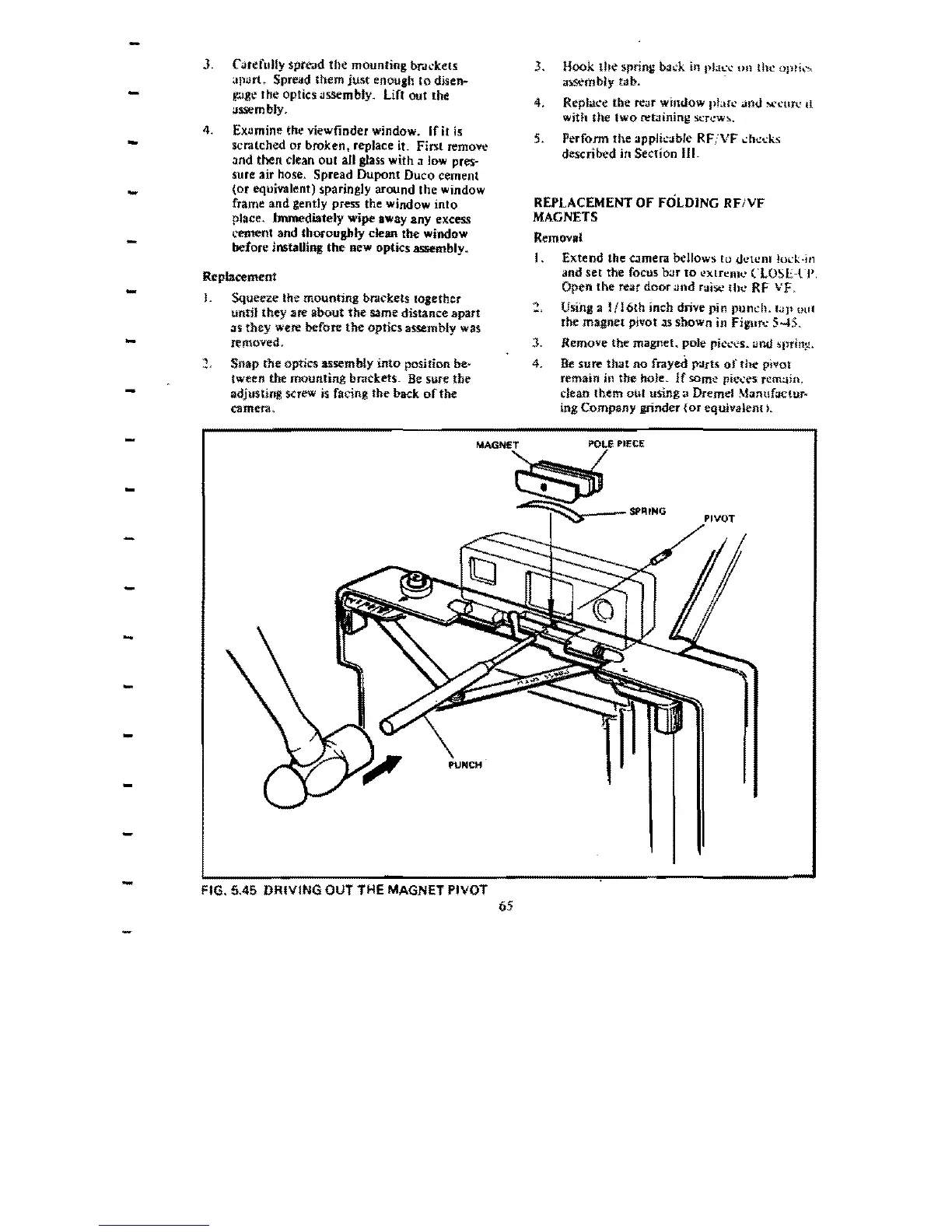
I.
Extend the
arnera
bellows
£0
d1."lCnl
1000.:k·111
and
set
the focus b:Jr
to
extrcmt.'
CLOSE-rp.
Open
the
fei:lr
door
nnd raise till! RF
vF"
USing
a
!fl6th
inch drive pin punch.
tap
out
the
magnet
pivot.1S
sbown
in FiplJ'l: 5-15.
l.
Remove the magnet. pole
pit."CC's.
:Jlld
spri!1~,
4.
Be
sure
that
no
frayed tydrts
of
the
pivot
remain jn
the
hoJe.
If
SOmo;!
pie<es
rem~in,
dean
[hem
out
using a Dremel
ManufaClur~
ing
Company
grinder
(or
equivaiem).
PIECE
FIG. 5.45 DRIVING OUT THE MAGNET PIVOT
65
 Loading...