-
IF
THE
VERTICAL LINES
DO
NOT
NOTE: If you have difficulty m<lking a good" top-
MERGE:
Using
an
appropriate tool. adjust
the
range screw
(Figure
5-46) unrjl
the
verti-
-
calUnes
in
the target meet.
IF
THE
HORIZONTAL
LINES
DO
NOT
-
MERGE:
Using
an
appropriate tool, adjust
the topside
screw (Figure
546)
until the hor-
izontal
J.ines
in
the target meet.
-
c.
Swing
the camera around to the four-foot
target.
While looking through
the
focal plane
plate loupe, move
the
focus bar toward
-
CWSE-lJP. Stop focusing
when
the image
is sharpest.
Now,look
at the larger crosshair
target through
the
RF /VF eye window:
IF
'l1lE
IMAGES
OF
THE
VERTICAL
LINE
-
ARE
NOT
MERGED: Using an appropriate
tool,
adju.t the
""""
screw
(Figure
546)
-
until the
images
of
the vertical tine
merge.
IF
'l1lE
IMAGES
OF THE HORIZONTAL
LINE
ARE
NOT
MERGED:
Using
an appro-
priate tool. adjust
the
topside screw (Figure
546)
until
the
images
of
the
honaontalline
merge.
d.
Go
back
to the infinity taraet and repeat the
infinity check (step
b).
e. When all a(ljustments are complete, seal
the
-
adjusting screws with shellac.
side adjustment, check
the
RF/VF
magnet.
On
some
cameras the magnet
pivOI
(Figure
545)
has
a slotted head which can
be
turned. changing the
po$ition
of
the magnet. DOing
this
may
help
in
bringing in topside.
f.
Take
the
camera
off
the collimator and
re-
place the cover plate and the cover on the
RF/VF
using
their retairting screws.
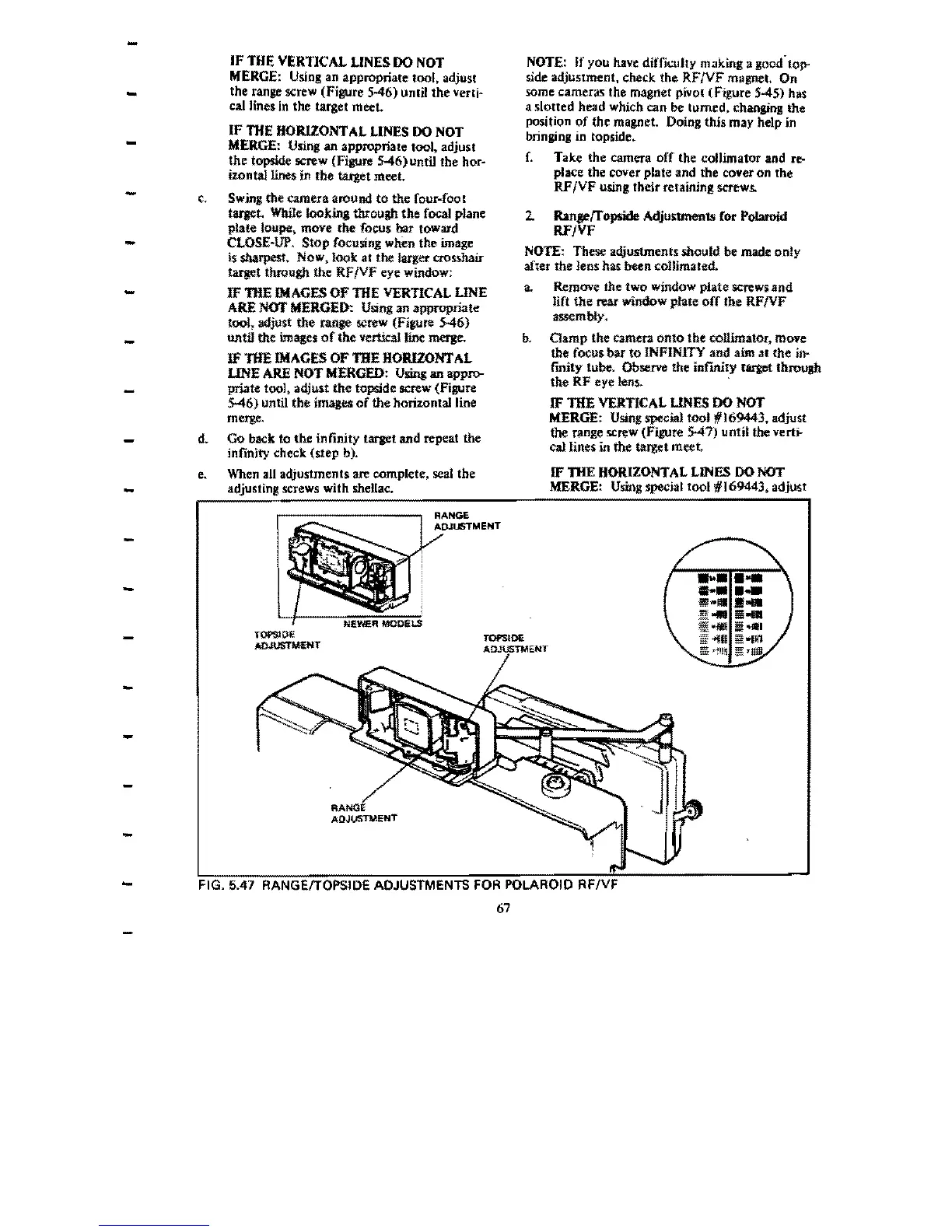
2.
Ranl!"rropslde AdjustmenlS ror Polaroid
RF/VF
NOTE: These adjustments should be made only
after
the
lens has been
co1Umated.
a.
Remove the two window pIate
screwund
lift the
roar
window plate off the RF/VF
assembly,
b.
Clamp
the
camera
onto
the
collimator. move
the
focus b.,. to INFINITY and
aim
at the in-
fmity tube. Observe the inf1Rity target
throush
the
RF
eye lens. "
IF THE VERTICAL
LINES
00
NOT
MERGE:
Using
special tool
11'169443,
adjust
the
range screw (Figure
547)
unti~
the vertj.
cal
lines in the target meet.
IF THE HORIZONTAL LINES
DO
NOT
MERGE:
Using
special tool #169443, adjust
RANGE
ADJUSTMENT
-
_
...
......
-
......
........
"l1li
iII.11I1
TOF'SJOE
4111
~
"1111
ADJUSTMENT
§f
'~Hn
§
'11111
-
-
-
-
-
ADJUSTMENT
RFIVF
67
 Loading...