Matrix 424, 832, 832+ Installation Manual
Page 8 RINS918-6
2. WIRING DIAGRAMS
GLOBAL TAMPER CONNECTION
Note: The global tamper connections are very important.
The global tamper connections on the 832 and 832+ control panel are GT and AUX-, devices
should be connected between these two terminals to create a global tamper loop.
The 424 control panel does not have the GT terminal connection, so a spare zone programmed
as Tamper should be used to create the tamper loop.
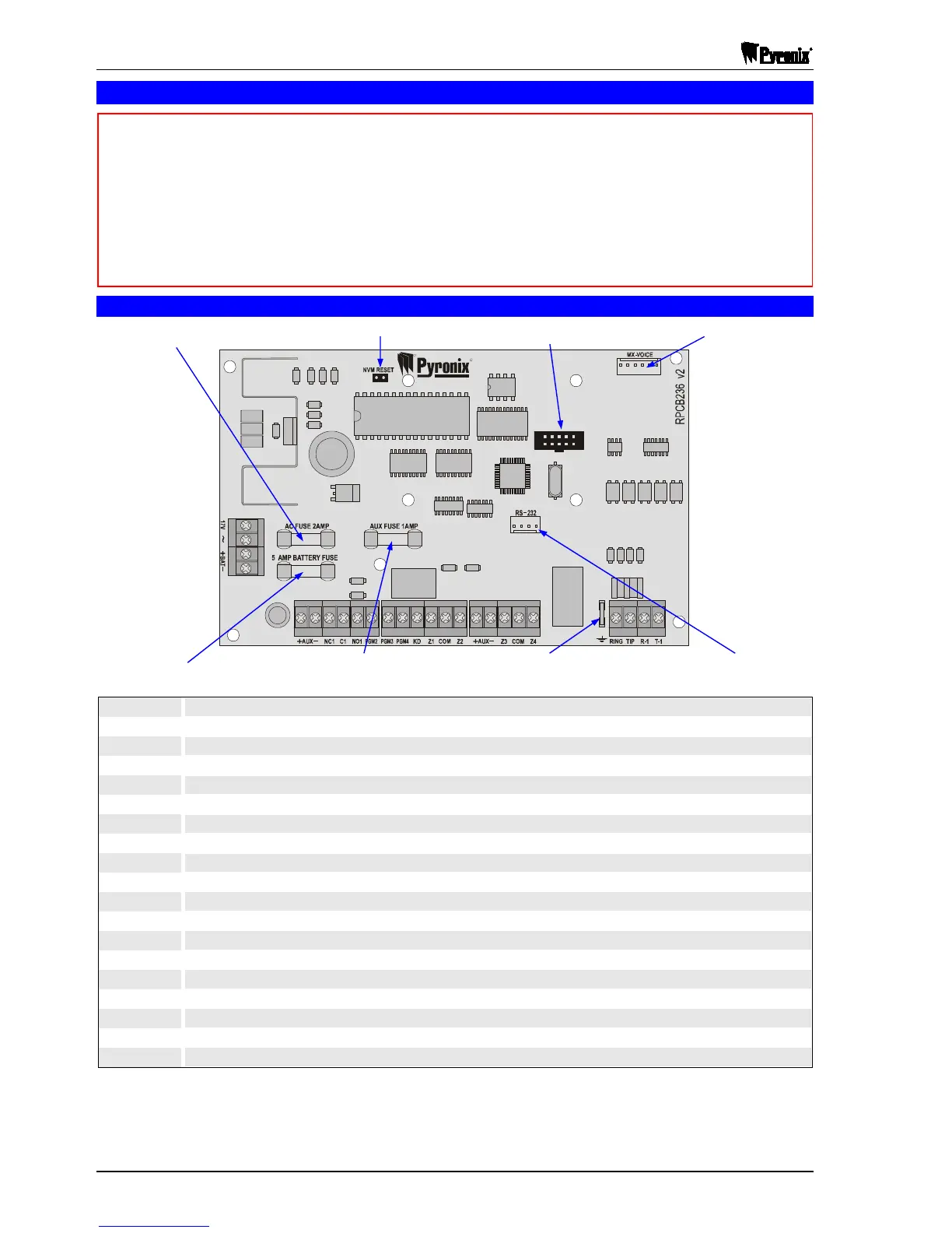
2.1 Matrix 424 PCB
17V~
Mains transformer connections 17VRMS, 21VA or 17V DC, 1.25A supply unit. Protected by a 2A fuse
+BAT-
Battery connections in order for the Matrix to operate without mains supply. Protected by a 5A fuse
+AUX-
Auxiliary supply to the bell. Protected by a 1A fuse
NC1
Programmable relay output 1. Normally closed contact
C1
Programmable relay output 1. Common contact, 30V@3A
NO1
Programmable relay output 1. Normally open contact
PGM2
Programmable output 2. Open collector, 12V@200mA
PGM3
Programmable output 3. Open collector, 12V@200mA
PGM4
Programmable output 4. Current sink, 12V@10mA (current limited to 50mA)
KD
Keypads / expanders data line
Z1
Zone 1 input
COM
Common connection for zones (0V)
Z2
Zone 2 input
+AUX-
Auxiliary supply for detectors, keypads, etc. Protected by a 1A fuse
Z3
Zone 3 input
COM
Common connection for zones (0V)
Z4
Zone 4 input
RING, TIP
Connections to analogue PSTN telephone line
R-1, T-1
To be connected to remaining telephone line equipment within the installation
R
R
NBUSJY
424
2A AC Supply
Input Fuse
Plug-On Zone Expander
Connector
M

 Loading...