Matrix 424, 832, 832+ Installation Manual
Page 34 RINS918-6
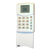
2.13.5 TWIN ALERT Internal Sounder Connection to Matrix 832 (832+)
NOTE: Terminal connections to Matrix 832+ are the same as to a Matrix 832.
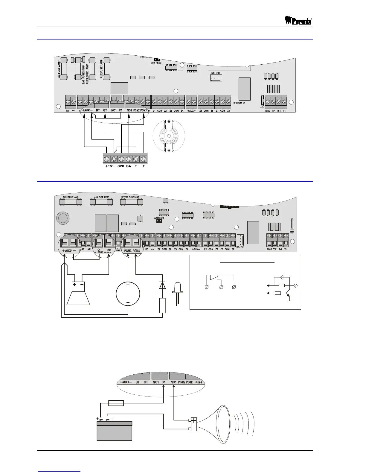
2.13.6 Buzzer, LED & Any Siren Connection to Matrix
NOTE: Terminal connections to Matrix 424 and 832+ are the same as to a Matrix 832.
12V
Buzzer
12V
Siren
C(-)
C(-)
A(+)
A(+)
1K
LED
PGM Output Stage Diagram
Relay Output
C1
(C2)
NO1
(NO2)
NC1
(NC1)
Contacts position when output is OFF
(relay coil is de-energised)
Transistor Output
10K
4K7
+Supply
PGM
NOTE 1: Buzzer 12V@200mA may be connected to any of the programmable outputs, except PGM 4.
Siren 12V@500mA must be connected to relay PGM output. LED may be connected to any of the
programmable outputs.
NOTE 2: When a high power siren is to be connected to the Matrix, PGM1 should be used. This output
uses a relay to switch up to a maximum 3A DC current capacity, allowing the use of an additional
battery to power the siren as shown in the diagram below.
Battery
FUSE
3A Anti-Surge
High Power Siren
15W, 30W
MATRIX 832 PCB
TWIN ALERT
win Alert must be connected to Matrix panel as
illustrated. PGM3 must be programmed as “Twin Alert”.
In this illustration PGM1 should be programmed as

 Loading...