Matrix 424, 832, 832+ Installation Manual
Page 26 RINS918-6
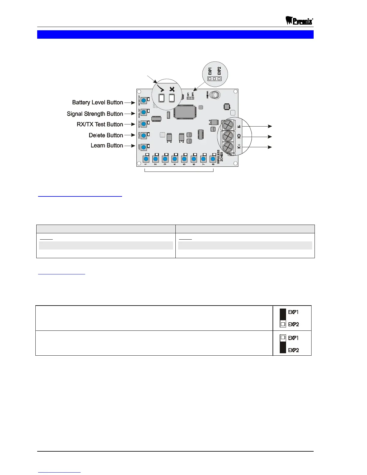
2.11 Matrix Wireless Expanders
NOTE: When connecting RIX modules to the bus, you must make sure you do not exceed the
maximum KEN number for the cable run. See Section 1.9 on page 4.
To Matrix PCB:
Signal/Battery
strength LEDs
Zone Buttons & Associated Zone LEDs
(K-)
(KD)
(K+)
Expander
Address
To Matrix PCB:
Signal/Battery
strength LEDs
Zone Buttons & Associated Zone LEDs
(K-)
(KD)
(K+)
Expander
Address
To Matrix PCB:
Signal/Battery
strength LEDs
Zone Buttons & Associated Zone LEDs
(K-)
(KD)
(K+)
Expander
Address
Signal/Battery Strength LEDs
The signal strength LEDS show two states, the signal strength and the battery levels of each zones. The table
below shows the different states.
Testing Signal Strengths: Testing Battery Levels:
LEDS LEDS
GREEN
= Signal Strength GOOD
GREEN
= Battery Level GOOD
RED
= Singal Strength BAD
RED
= Battery Level BAD
Zone Addressing
It is possible to have up to two wireless expanders on any one Matrix Wireless System. If two expanders are
installed on a single Matrix wireless system, they need to be different IDs. One expander should be set to
EXP1 and the other should be set to EXP2.
Setting to EXP1 maps the 8 wireless expander onto
Zones 17-24
on the Matrix alarm panel.
Setting to EXP2 maps the 8 wireless expander onto
Zones 25-32
on the Matrix alarm panel.

 Loading...