Matrix 424, 832, 832+ Installation Manual
Page 4 RINS918-6
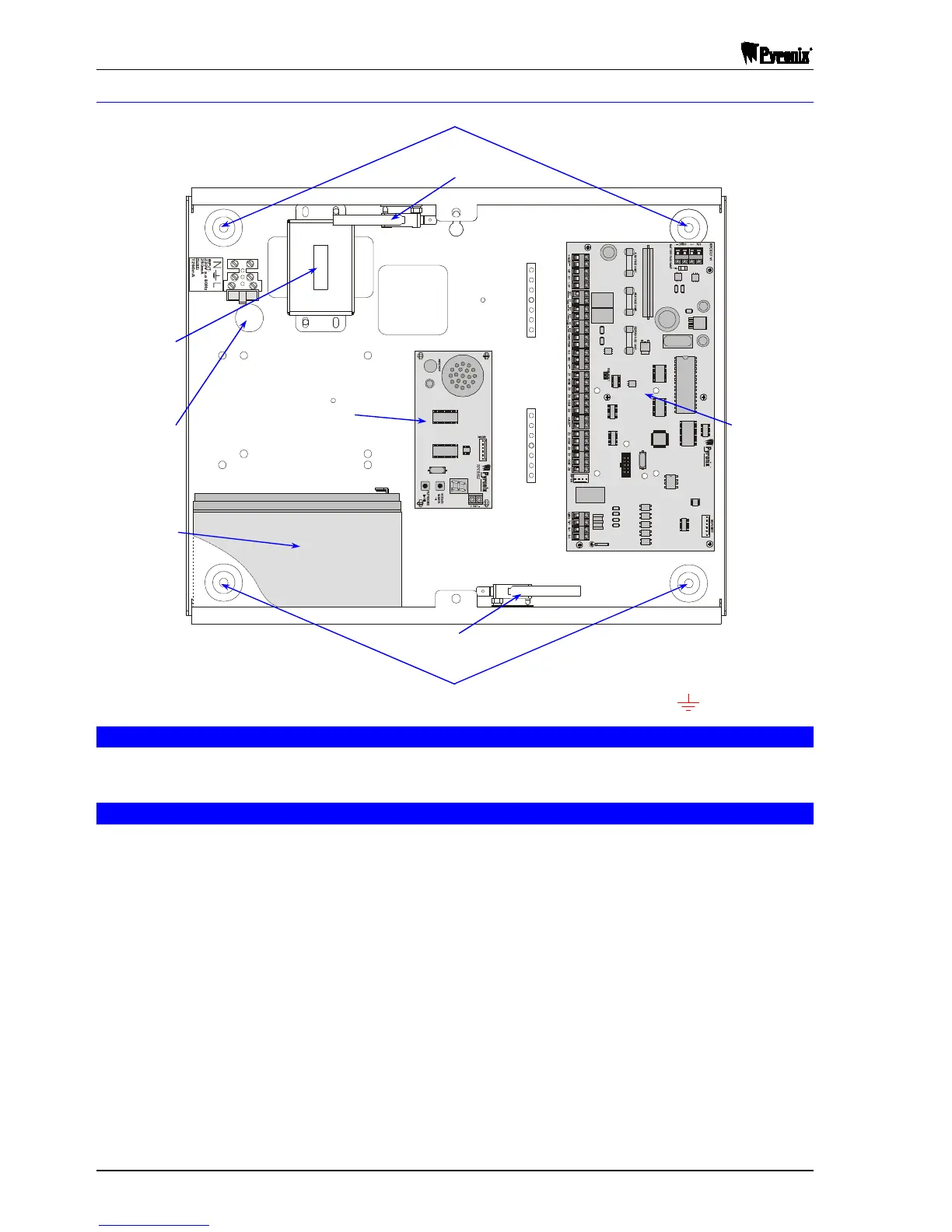
1.7.2 Panel Layout – Metal Case
1.8 Battery Installation Procedure
Place two foam pads on the bottom of the battery and two on the upper rear. Place the battery in the case
and secure with two tie wraps.
1.9 Cabling Rules for the Matrix Bus
Care must be taken when connecting devices to the bus over long cable runs. This is to ensure maximum
system integrity under all circumstances (battery backup, etc.). Pyronix recommends using standard 0.22mm
cross sectional area, shielded multi-core alarm cable for the Matrix bus.
The maximum number of external devices connected to the bus on any one system is limited to
six - this may not be exceeded. Although six is the system limit other restrictions apply to each cable run. It
is important to restrict the amount of current carried along each length of cable to limit voltage drops across
the system. Apart from being affected by current magnitude, voltage drops are also dependent upon the
length of cable and the types of devices fitted. The following tables provide a means of determining suitable
cable run configurations for different systems.
NOTE: It is the length of cable between panel and end device that is important rather than the overall
length on the entire bus.
R
R
NB

 Loading...