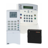
Matrix 424, 832, 832+ Installation Manual
RINS918-6 Page 1
1. INSTALLATION & CABLING RULES
Before mounting the panel you must decide on the place of installation. The use of remote keypads mean
that the panel can be located anywhere on the premises and it is recommended that the panel be housed in a
concealed place.
IMPORTANT:
1. Before any work is undertaken it is highly recommended that the mains supply be isolated to
reduce the risk of electric shock.
2. Before handling or touching any of the bare PCBs, you should make every effort to reduce the
amount of static electricity that the boards may be exposed to.
1.1 Tools Required
The Matrix alarm panel and associated devices use standard screws for all serviceable parts. No other special
tools are required.
Action / Serviceable Part Tool Required
Remove the case lid (panel + expanders) Pozi-drive No.3
Mains input terminals Slotted 4mm
Zone terminals (panel and expanders) Slotted 3mm
Battery terminals on main PCB Slotted 3mm
MX-BATT terminals Slotted 3mm
Remove LCD/ICON keypad rear cover Pozi-drive No.0
1.2 Mains Wiring
The matrix panel has a standard 3-way mains input connector block with integrated supply fuse protection.
The connector block connections are indicated on the panel case with an associated mains input sticker. This
sticker indicates Live (L), Neutral (N) and Earth, as well as the mains supply voltage rating.
1.3 Zone/PGM Wiring
To minimise false signals on the zone connections it is recommended that no part of the wiring be allowed to
short to adjacent connectors. Strip back only enough sleeving from the wire as necessary before inserting it
all the way into the connector, as far as it will go. When placing more than one wire into a single terminal
make sure that all the wires are pushed in firmly as far as they will go, before tightening the terminal screw.
Do not join multiple wires together before inserting into the terminal block, as this is a common cause of
faulty wiring causing false alarms.
When linking out unused zones with resistors, again make every effort to ensure that adjacent resistors
cannot short out with each other. Keep the resistor leg length short and do not allow resistor legs to overlap
with each other.
1.4 Battery Wiring
The battery wiring is very similar to the zone/PGM wiring as the same type of terminal connections are
employed. If you are using an MX-BATT battery monitor board then you will be wiring to the MX-BATT BAT
IN connector and not to the Matrix alarm panel PCB.
The battery connection is polarized. You must ensure that the positive terminal of the battery is connected to
the BAT+ terminal on the Matrix alarm panel (BAT IN+ on the MX-BATT PCB), and that the negative terminal
of the battery is connected to the BAT- terminal on the Matrix alarm panel (BAT IN – on the MX-BATT PCB).
1.5 Battery Maintenance
The Matrix alarm panel constantly monitors the battery voltage and will provide suitable battery low/fail
warnings in the event of a battery problem. A system fault 4 indicates a low battery. System fault 3 indicates
a missing/dead battery. When replacing a battery only use the recommended battery type and rating. See the
Technical Specification Section for full details.

 Loading...