Matrix 424, 832, 832+ Installation Manual
Page 10 RINS918-6
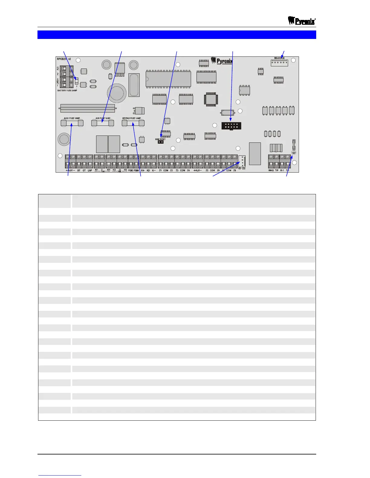
2.3 Matrix 832+ PCB
17V~
Mains transformer connections 17VRMS, 44VA for a metal casing / 21VA for a plastic casing or 17V
DC, 1.25A supply unit. Protected by a 2A fuse
+BAT-
Battery connections in order for the Matrix to operate without mains supply. Protected by a 5A fuse
+AUX1-
Auxiliary supply to the bell. Protected by a 1A fuse
BT
Bell Tamper – Negative tamper return from bell box (normal condition connected to 0V)
GT
Global Tamper – Negative tamper return (normal condition connected to 0V)
LNF
Telephone line fail input
NC1
Programmable relay output 1. Normally closed contact
C1
Programmable relay output 1. Common contact, 30V@3A
NO1
Programmable relay output 1. Normally open contact
NC2
Programmable output 2. Normally closed contact
C2
Programmable output 2. Common contact, 30V@3A
NO2
Programmable output 2. Normally open contact
PGM3
Programmable output 3. Open collector, 12V@200mA
PGM4
Programmable output 4. Current sink, 12V@10mA (current limited to 50mA)
K+
Positive supply for keypads / expanders. Protected by a 1A fuse
KD
Keypads / expanders data line
K-
Negative supply for keypads / expanders.
Z1
Zone 1 input
COM
Common connection for zones (0V)
Z2
Zone 2 input
Z3
Zone 3 input
COM
Common connection for zones (0V)
Z4
Zone 4 input
+AUX-
Auxiliary supply for detectors, etc. Protected by a 1A fuse
Z5
Zone 5 input
COM
Common connection for zones (0V)
Z6
Zone 6 input
Z7
Zone 7 input
COM
Common connection for zones (0V)
Z8
Zone 8 input
RING, TIP
Connections to analogue PSTN telephone line
R-1, T-1
To be connected to remaining telephone line equipment within the installation
R
R
NBUSJY
832+
5A
Battery Fuse
Plug-On Zone Expander
Connector
M

 Loading...