Chapter 3 Standard Radar Operations 53
Maximum Number of Range Ring
Range (nm) Range Rings Interval (nm)
1
/
8
2
1
/
16
¼ 2
1
/
8
½ 4
1
/
8
¾ 3 ¼
1½ 6 ¼
36½
661
12 6 2
24* 6 4
48* 6 8
72* 6 12
* The maximum range depends on your scanner type, as detailed in the Pathfinder Radar
Scanner Owner’s Handbook.
The number of range rings shown in the table is the number to the selected
range. Additional range rings are displayed to the edge of the radar picture, at
the standard ring interval for the current range, and are most noticeable when
the centre is offset.
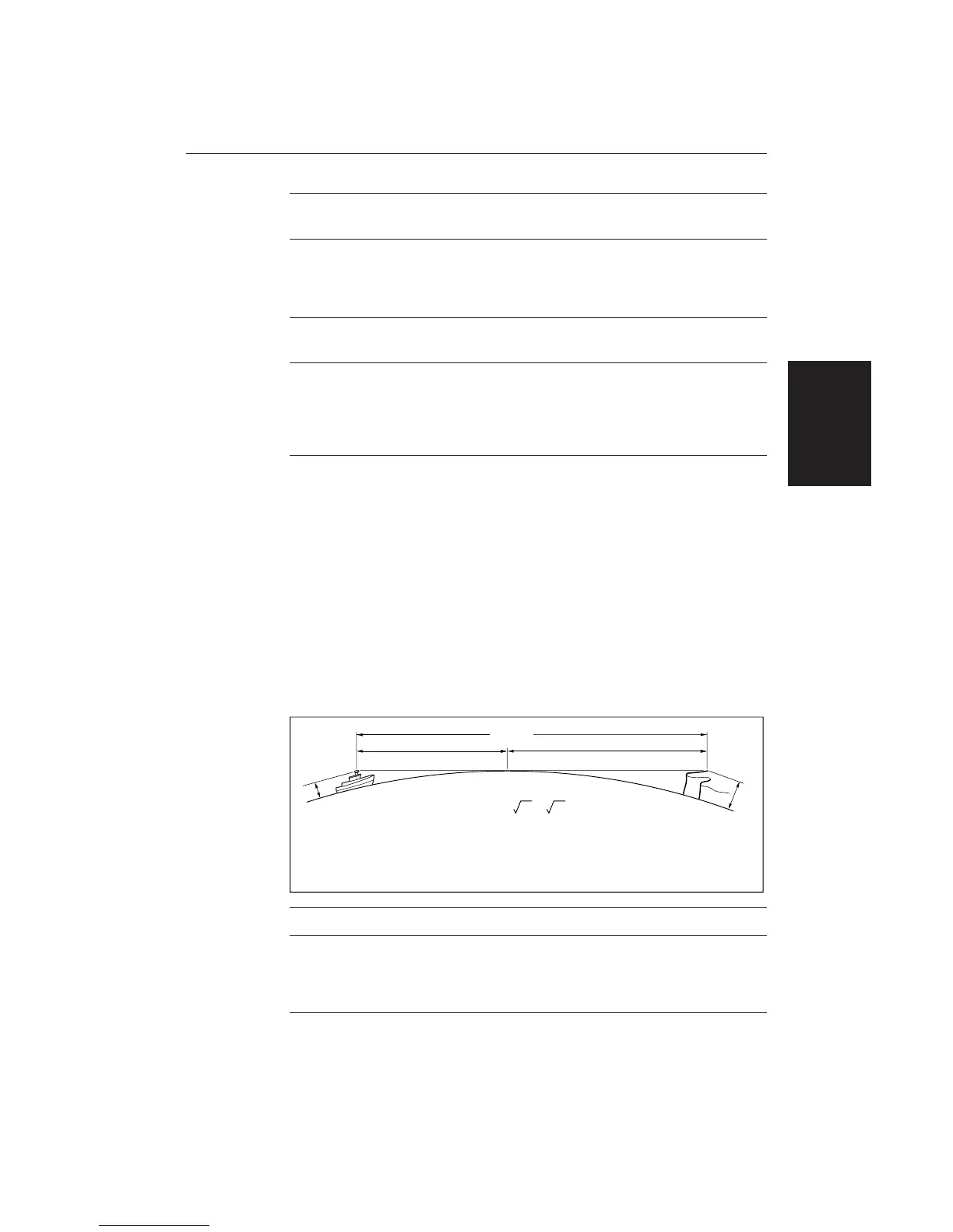
Determining Actual Radar Range
The actual maximum radar range is essentially line-of-sight, and is limited by
the height of the scanner and the height of the target as shown in the following
diagram. The table below lists some range examples:
a
1
a
2
Earth
h
H
Cliff
Radar
D1643-2
R
max
R
max
= 2.23 ( h + H )
R
max
h
H
maximum radar range
radar antenna height
target height
in nautical miles
in metres
in metres
R
max
= radar horizon of antenna (
a
1
) + radar horizon of target (
a
2
)
Antenna Height Target Height (m) Maximum Range (nm)
3m 3m 7.8
3m 10m 10.9
5m 3m 8.9
5m 10m 12.0
Note: The ranges shown in the table are theoretical maximum ranges. The
radar horizon is greater than the optical horizon, but the radar can only detect
targets if a large enough target is above the radar horizon.
Determining
Actual Radar
Range

 Loading...