EasyManuals Logo
Home>RayTek>Measuring Instruments>Thermalert GP series

RayTek Thermalert GP series User Manual

RayTek Thermalert GP series
84 pages
To Next Page IconTo Next Page
To Previous Page IconTo Previous Page
Page #13 background imageLoading...
Page #13 background image
4. Secure the monitor to the panel by tightening both fixing clamp screws
until the flanges are snug against the back surface of the panel.
5. Connect the terminal cable as described in the following section.
6. After you complete the electrical installation, secure the rear cover to the
back of the monitor. (Do not operate with rear cover removed because of
electrical shock hazard.)
2.3 ELECTRICAL INSTALLATION
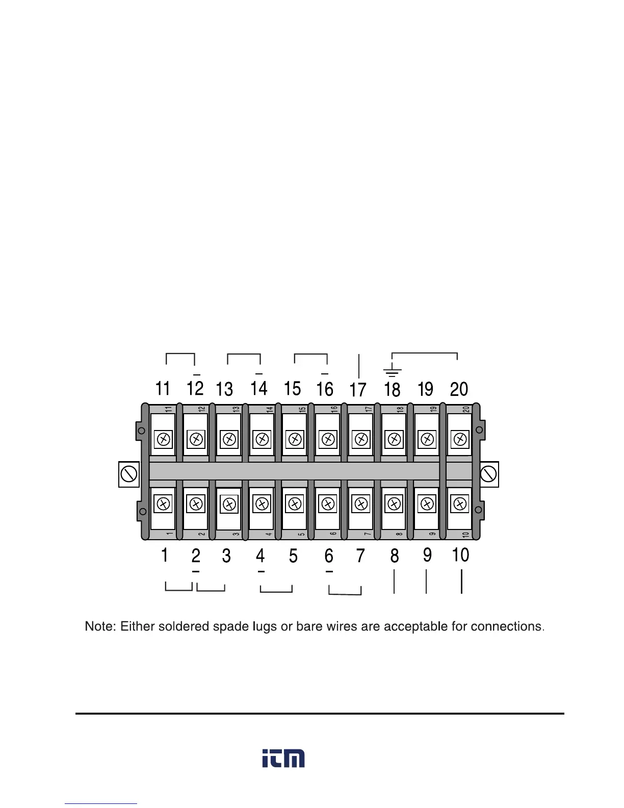
2.3.1 Terminal Block Layout
The terminal block layout is shown in Figure 3. (Terminal definitions are on
the following page.)
SP1 SP2 RST NC Power
+ + + N H
+ + + +
mA out TC out Input 1 Input 2 SHD 24V Input3
Figure 3: Terminal Block Layout
Thermalert GP Series Operator’s Manual 5
www. .com
information@itm.com1.800.561.8187

Table of Contents

Questions and Answers:

Question and Answer IconNeed help?

Do you have a question about the RayTek Thermalert GP series and is the answer not in the manual?

RayTek Thermalert GP series Specifications

General IconGeneral
BrandRayTek
ModelThermalert GP series
CategoryMeasuring Instruments
LanguageEnglish