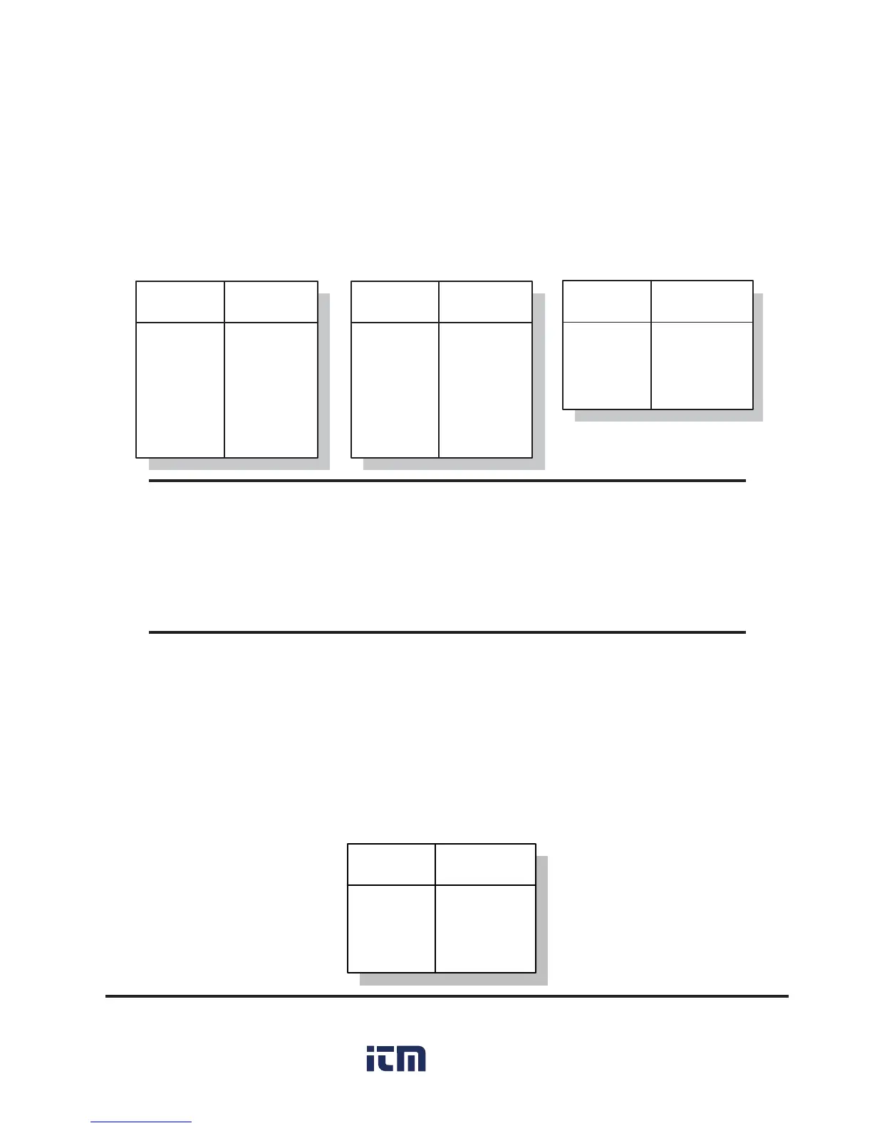
Table 3: Power Connections
Table 2: Wiring Devices that Use Power from Monitor
6
6
7
8
9
Power (-)
Signal (-)
Signal (+)
Shield
Power (+)
TERMINAL
NUMBER
FUNCTION
6
6
8
9
10
Power (-)
4-20mA (-)
Shield
Power (+)
4-20mA (+)
TERMINAL
NUMBER
FUNCTION
0-5V 4-20 mA
8
9
10
Shield
Power (+)
4-20mA (-)
TERMINAL
NUMBER
FUNCTION
2-Wire 4-20 mA
WARNING
1. Incorrect wiring can damage the monitor and void the warranty.
Make sure to unplug the unit before wiring devices or power.
2. The unit be used in a closed cabinet to prevent electrical shock!
Refer to Section 2.4.2 for information on setting up parameters on the GP
Monitor for 0-5 volt, 4-20 mA devices and thermocouples.
2.3.3 Power Connections
You can connect 110-220VAC, 50-60Hz, to the monitor. It can automatically
sense whether you connect 110 or 220 VAC. Use Table 3 as a guide.
Use Table 2 when connecting either 0-5V or 4-20mA input devices that can
use the 24VDC/50mA power available from the monitor.

 Loading...