8 Thermalert GP Series Operator’s Manual
2.3.5 Relay Accessory
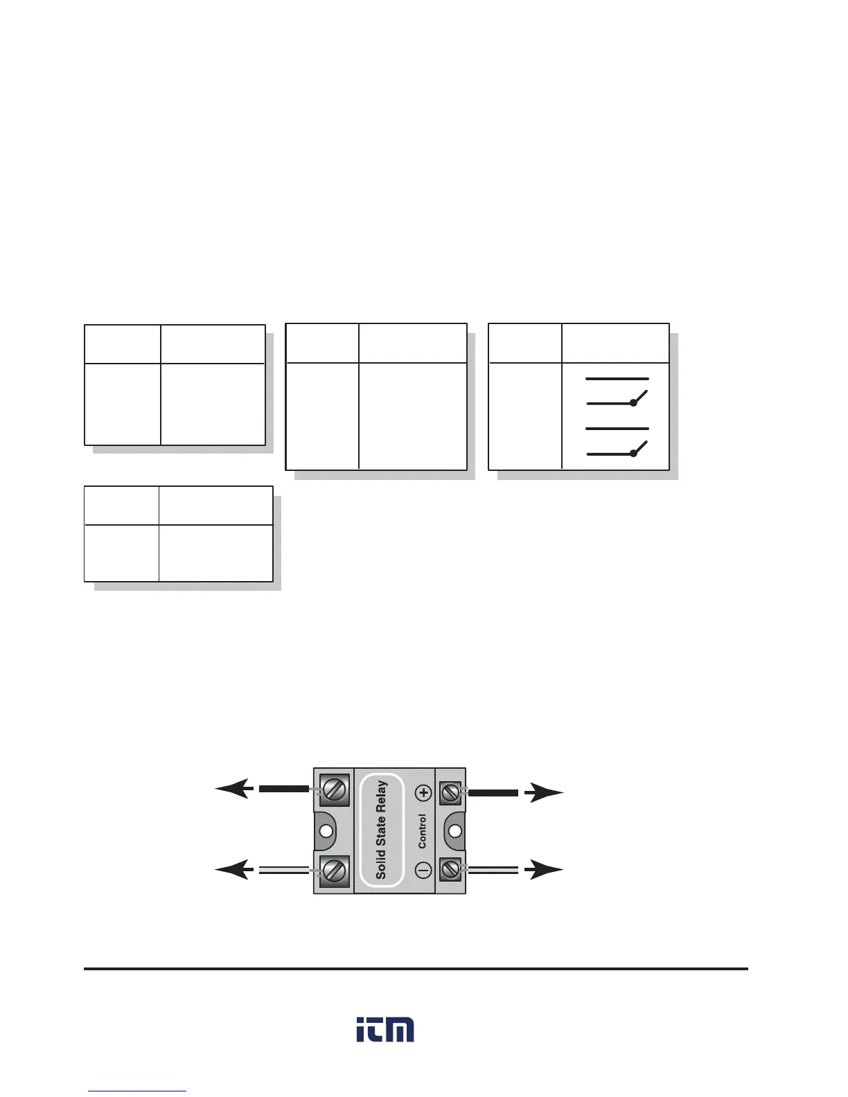
A solid state relay accessory is available as a switching output for Setpoint
use as a control for an alarm or triggering mechanism. The Thermalert GP
Setpoint output can supply 15mA @ 5V for SSR control. A wiring diagram
for the relay accessory is shown in Figure 4.
Figure 4: Relay Accessory Wiring
To GP Monitor
Terminal 11 or 13
(Setpoint 1 or 2)
To GP Monitor
Terminal 12 or 14
(Digital Ground)
To Alarm or
Controlling Device
Two relays are necessary to take advantage of both setpoints.
Table 4: Output Connections
TERMINAL
NUMBER
FUNCTION
11
12
13
14
Digital ground
Setpoint 1
Digital ground
Setpoint 2
Setpoints 1 & 2
1
2
8
4-20mA output
Analog ground
Shield
TERMINAL
NUMBER
FUNCTION
TERMINAL
NUMBER
FUNCTION
11
12
13
14
Optional Dual Relays
4-20 mA
TERMINAL
NUMBER
FUNCTION
2
3
Thermocouple -
Thermocouple +
Thermocouple
2.3.4 Output Connections
The monitor has the following outputs (connections shown in Table 4):
•4 – 20mA
• Thermocouple outputs (J, K, E, N, T, R, and S)
• Setpoints 1 and 2

 Loading...