The “N” indicator, on the left side of the panel, when lit, shows that the unit
is working normally. The “O” and “L” indicators are controlled by Setpoints
1 and 2 (SP1, SP2). The “O” indicator, when lit, shows that the measured
temperature or value exceeds the current SP1 or SP2 setting. The “L” indica-
tor, when lit, indicates that the measured temperature or value is lower than
the current SP1 or SP2 setting.
On the right side of the panel are two indicators that show which tempera-
ture value the unit is set to if temperature sensors are attached to the moni-
tor. The “C” indicates if the temperature measurement is in degrees C
(Celsius). The “F” indicates if the temperature measurement is in degrees F
(Fahrenheit). For 0-5 volt and 4-20 mA devices that do not measure tempera-
tures, C and F can both be turned off.
Thermalert GP Series Operator’s Manual 9
2.4 OPERATION
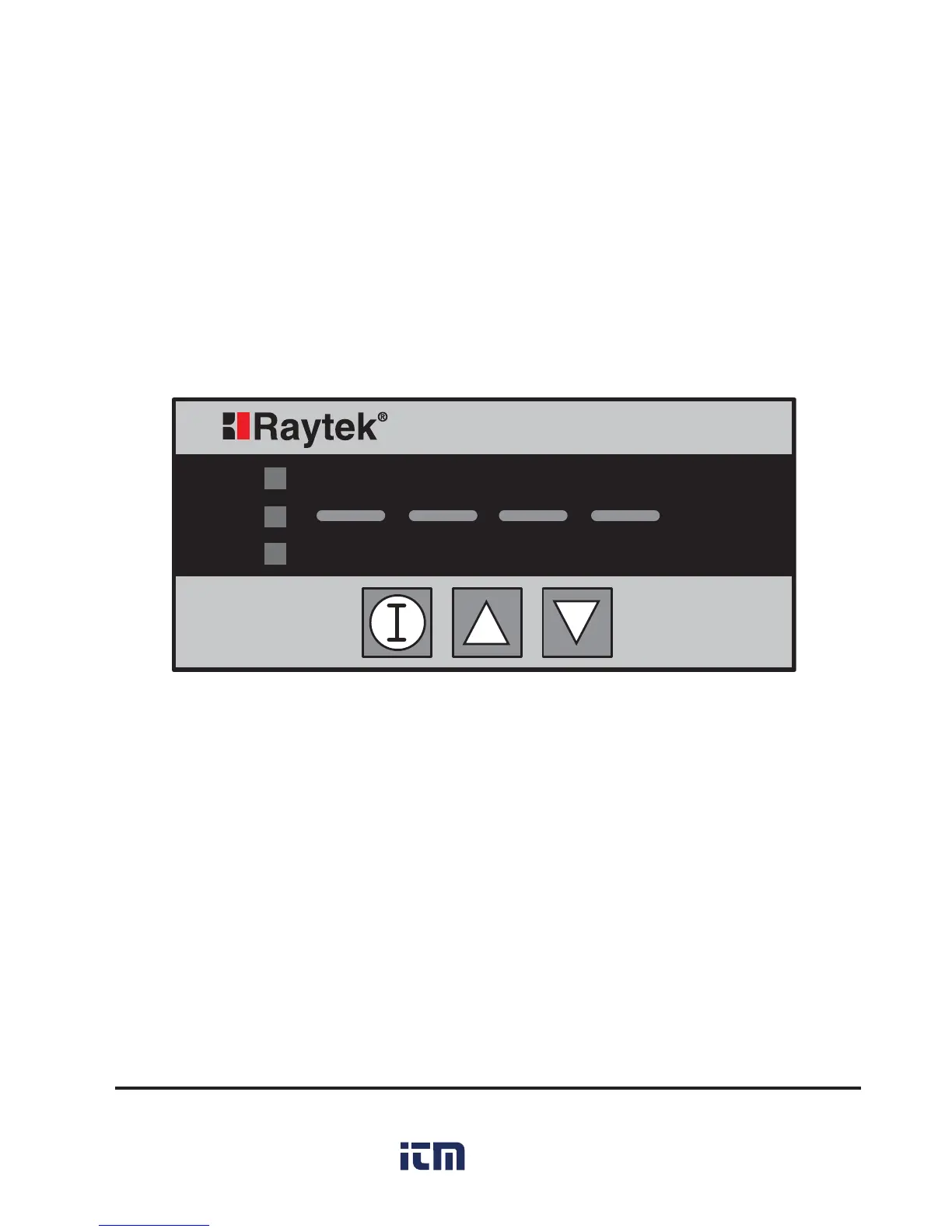
The Thermalert GP Monitor consists of a control panel with 4 LEDs, 3 but-
tons, and 5 indicating lights. Besides displaying the current temperature or
user-defined value, the LEDs also display parameter settings. By using the “I”
key and the up and down arrow keys you can control the different functions,
and the indicator LEDs show the function being addressed. Figure 5 shows
the startup screen when power is first turned on (no information stored on
EEPROM), or when factory defaults are restored (see Section 2.4.12).
O
N
L
C
F
Thermalert GP
Figure 5: The Control Panel Startup Screen

 Loading...