for disinfection should be fl ushed thoroughly before using for pressure testing
of drinking water pipes. Hydrogen peroxide decomposes in time and loses its
effect depending on the environment in which it is stored. Therefore the concen-
tration of the dosing solution should be checked for effectiveness before every
disinfection. To do this, fi ll a clean, sealable container with 100 ml of water and
draw 1 ml of dosing solution from the bottle using the pipette provided with
every carton of REMS Peroxi Color and add it to the container (ratio 1:100).
Seal the container and shake well. The concentration of the container contents
is measured with the test strip (Art. No. 091072) according to the instructions
printed on the test strip package. This should be ≥ 150 mg/l H
The built-in nozzles for automatic dosing by REMS V-Jet TW and REMS V-Jet
H are different and are adapted to the properties of the ingredients to be injected.
Therefore please always observe the intended use.
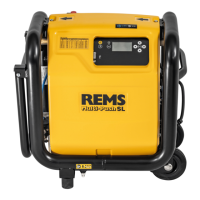
Only connect the cleaning and preservation unit (Fig. 7) to the fl ushing drain
of REMS Multi-Push (Fig. 4 (15)). Never allow cleaner or corrosion protection
agent to fl ow though the pipes of REMS Multi-Push.
2.6.1 Leak and load testing with compressed air according to information leafl et
2.6.1 Leak and load testing with compressed air according to information leafl et
“Leak tests of drinking water installations with compressed air, inert gas or
“Leak tests of drinking water installations with compressed air, inert gas or
water” (January 2011) of the German Central Association for Sanitary, Heating
water” (January 2011) of the German Central Association for Sanitary, Heating
and Air Conditioning (ZVSHK)
and Air Conditioning (ZVSHK)
the information leafl et “Leak Tests of Drinking Water Installations
with Compressed Air, Inert Gas or Water” (January 2011) of the German Central
Association for Sanitary, Heating and Air Conditioning (ZVSHK) defi nes the
following for the national regulations under “3.1 General”:
“Due to the compressibility of g
ules for the prevention of accidents
“Working on Gas Systems” and the “Technical Rules for Gas Installations
DVGW-TRGI” must be observed for physical and safety reasons when conducting
pressure tests with air Therefore, the test pressures have been defi ned as
maximum 0.3 MPa/3 bar/43.5 psi, the same as for load and leak tests for gas
pipes, in agreement with the responsible industrial liability insurance associa-
tion and based on these rules. The national
ions are thereby fulfi lled.”
The respective national safety provisions, rules and regulations valid for
the application site must be considered and observed.
Before conducting a test with compressed air, it must be assessed whether the
installation to be tested will withstand the preset/selected test pressure “p refer”.
ed air hose (Fig. 4 (23)) to the output Pressure test with
compressed air, Disinfection, Cleaning, Preservation, Compressed air pump
(22) and connect the compressed air hose (23) to the installation to be tested.
2.6.2 Pressure and leak testing of drinking water installations with water in
2.6.2 Pressure and leak testing of drinking water installations with water in
accordance with EN 806-4:2010 (REMS Multi-Pus
accordance with EN 806-4:2010 (REMS Multi-Pus
The hydro-pneumatic water pump installed additionally in the REMS Multi-Push
SLW for this test is fed by the built-in compressor of the REMS Multi-Push.
hydro-pneumatic water pump generates a water pressure of max. 1.8 MPa/18
bar/261 psi. Before conducting one of the tests with water according to method
A, B, C, it must be assessed whether the installation to be tested will withstand
the preset/selected test pressur
EMS fi ne fi lter (12) (Art. No. 115609) with fi lter cartridge 90 µm after
the house connection (water meter) (Fig. 3). Connect the suction/pressure hose
(13) to the pressure test with water supply (Fig. 1 (24)) after the fi ne fi lter.
Connect the high-pressure hose (26) to the pressure test with water drain (Fig. 4
(25)) and connect to the installation to be tested. Feed the pressure relief water
(27) into a vessel (bucket).
2.6.3 Load and leak testing of gas pipe systems with compressed air in accord-
2.6.3 Load and leak testing of gas pipe systems with compressed air in accord-
ance with “Technical Rule Worksheet G 600 April 2008 DVGW-TRGI 2008” of
ance with “Technical Rule Worksheet G 600 April 2008 DVGW-TRGI 2008” of
the DVGW German Gas and Water Association, Germany
the DVGW German Gas and Water Association, Germany
For Germany, the technical rule for gas installations
“Technical Rule Worksheet
G 600 April 2008 DVGW-TRGI 2008”
of the DVGW German Gas and Water
Association defi nes the following among other things:
“5.6.2 Safety measures during the tests”: Safety measures may need to be
taken during the tests when carrying out the load test due to the compressibility
of gases. “The max. test pressure may not exceed the value of 3 bar. Every
sudden rise in pressure in the pipe system to be tested must be avoided.”
“5.6.3 Test media”: “The tests in accordance with ... can be carried out option-
ally with air or inert gas (e.g. nitrogen). …The use of oxygen is not permitted.”
(The test with inert gases cannot be carried out with REMS Multi-Push).
4 Pipe systems with operating pressures up to and including 100 mbar ...
are subjected to the following tests:
c) Usefulness test for systems in operation” (this cannot be carried out with
load test must be carried out before the leak test …” “The test
pressure is 1 bar and may not drop during the test time of 10 minutes.” “The
uring device must have a minimum resolution of 0.1 bar”.
“5.6.4.2 The leak test must be carried out after the load test...” The test pres-
sure must be 150 mbar and may not drop for the duration of the test.” The
measuring device must have a minimum resolution of 0.1 mbar. Table 11
specifi es “Adaptation times and test duration depending on pipe volume”:
Table 11 – Adaptation times and test duration depending on the pipe
le of the legal German accident insurance must also be observed for
“Operation of work equipment”, BGR 500, April 2008, chap. 2.31,
industrial liability insurance association rule.
The respective national safety provisions, rules and regulations valid for
the application site must be considered and observed.
Before conducting a test with compressed air, it must be assessed whether the
installation to be tested will withstand the preset/selected test pressure “p refer”.
Connect the compressed air hose (Fig. 4 (23)) to the output Pressure test with
compressed air, Compressed air pump (22) and connect the compressed air
hose (23) to the installation to be tested.
2.7 Programs Ingredients \ Cleaning and preservation of heating systems
Before cleaning and preserving heating systems with REMS Multi-Push, safety
devices for the prevention of drinking water contamination by fl owback, e.g.
pipe network separator BA in accordance with EN 1717:2000 must be installed
to protect the drinking water against contamination.
Then fi t the REMS fi ne fi lter (Fig. 3 (12)) (Art. No. 115609) with fi lter cartridge
90 µm. Connect the suction/pressure hose (Fig. 1 (13)) to the fl ushing supply
(14) after the fi ne fi lter. Fit the REMS V-Jet H (Fig. 7) cleaning and preservation
unit for heating systems with supply (Fig. 7 (16)) to the fl ushing drain of REMS
Multi-Push (Fig. 4 (15)). Observe the direction of fl ow arrows. The main line of
the cleaning and preservation unit consists of the supply, pressure limiting valve
(17), non-return valve (18), drain to the heating system (19). This is connected
to the heating system to be cleaned by the suction/pressure hose (Fig. 4 (13)).
Part of the supply is pushed through the fl ow head (Fig. 7 (20)) into the bottle
(21) which contains the cleaner or corrosion protection for heating systems.
These are fed into the heating system to be cleaned o
ver allow cleaner or corrosion protection agent to fl ow though the pipes of
Do not use suction/pressure hoses for drinking water lines any more after they
have been used for heating systems.
8 Compressed air pump program
Vessels of all types can be pumped up with this p
rogram. Connect the compressed
air hose (23) to the output Pressure test with compressed air, Disinfection,
Cleaning, Preservation, Compressed air pump (Fig. 4 (22)) and connect it to
the vessel to be pumped up, e.g. expansion vessel, tyre. The value
0.02 MPa / 0.2 bar / 3 psi is preset.
anager program (data transfer)
The results of the fl ushing and test programs are saved with date, time and log
number in the selected language and can be transferred to a USB stick or
printer (accessory part no. 115604) (neither of which is included in the scope
of supply) for documentation (see
Unlike the described “Compressed Air Pump” program in which the values are
controlled by the electronic control, compressed air tools up to a max. air
Nl/min can be operated directly from the compressed air
vessel at the compressed air tools connection (Fig. 4 (28)). A compressed a
plings NW 7.2 must be used (available as an accessory).
REMS Multi-Push is not intended/suitable for permanent connection to the
installation. Disconnect all hoses from the installation after completing the work.
REMS Multi-Push may not be operated unattended.
ing the REMS Multi-Push, check whether the respective latest version
software is installed on the input and control unit. Select the Settings menu and
then Device data to display the version software. The latest version software
(Ver. Software) for the input and control unit is available by USB stick as a
download: www.rems.de → Downloads → Software → REMS Multi-Push →
Download. Compare the number of the version software of the unit with the
on software number and install the latest version software if neces-
 Loading...