GENERAL REMARKS
9
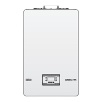
Description Condexa HPR boiler type
35 45 55 70 35 45 55 70 35 45 55 70
C4 C6 C8
Temperature of the ue gases in nominal conditions
(at 80/60°C) [°C]
58 59,8 48,8 56,9 72,2 75,5 68,8 76,0 55,3 56,7 45,9 54,4
Mass ow rate [m
3
/h] @ nominal output [kW]
3,77 4,864 5,989 7,702 3,816 4,849 5,799 7,486 3,929 4,976 5,93 7,759
Nominal output [kW]
35,4 45,47 57,11 73,51 35,78 45,44 55,22 71,28 36,86 46,56 56,54 74,07
Overtemperature of the ue gases [°C]
115
Temperature of the ue gases at minimum output [°C]
43,3 43,3 38,1 38,1 59,4 59,4 58,8 58,8 42,9 42,9 40,1 40,1
Mass ow rate at the minimum heat output [m
3
/h] @
reduced power [kW]
0,886 0,886 1,04 1,071 0,606 0,606 0,951 0,982 1,292 1,34 1,632 1,67
Minimum nominal output [kW]
8,3 8,3 9,92 10,21 5,66 5,66 9,08 9,37 12,09 12,54 15,54 15,9
CO
2
content in nominal conditions [%]
8,94 9,08 9,45 9,70 10,31 10,39 11,20 11,20 7,18 8,15 9,15 9,33
CO
2
at the minimum heat output [%]
5,40 5,40 6,02 6,02 10,01 10,01 11,07 11,07 4,00 4,00 5,32 5,32
Loss of minimum permitted pressure (in air feed and ue
gas pipe) [Pa]
15 23 19 34 - - - - - - - -
Loss of maximum permitted pressure (in air supply and
ue gas pipe) [Pa]
160 192 172 197 - - - - - - - -
Maximum permitted pressure difference between
combustion air inlet and ue gas outlet (including
wind pressure) [Pa]
- - - - 15 23 19 34 - - - -
Maximum permitted combustion air temperature [°C]
- - - - 45 45 45 45 - - - -
C9 35 45 55 70
Minimum effective diameter of the ue/utility
compartment [mm]
240
Notes
C1:
For the installation of the terminals on the wall and roof, refer to the specic instructions contained in the kits
.
The terminals emerge from separate combustion and air supply circuits within a square area of 50 cm.
C3: The terminals of the separate combustion and air supply circuits must lie within a square area of 50 cm, and the distance between the surfaces
of the two holes must be less than 50 cm.
C4: The boilers in this conguration, with the relative connection pipes, can be connected to only one natural draught stack.
Condensate ow inside the appliance is not permitted.
C5: The terminals for combustion air supply and the evacuation of ue gases must not be installed on opposite walls of the building.
C6: Condensate ow inside the appliance is permitted.
Maximum permitted recirculation rate of 10% in windy conditions.
The terminals for combustion air supply and the evacuation of ue gases must not be installed on opposite walls of the building.
This type of conguration is not permitted in some countries; refer to the local regulations in force.
C8: Condensate ow inside the appliance is not permitted.
 Loading...
