Rockwell Automation Publication ENET-IN002H-EN-P - August 2017 15
Install a 1756 EtherNet/IP Communication Module Chapter 1
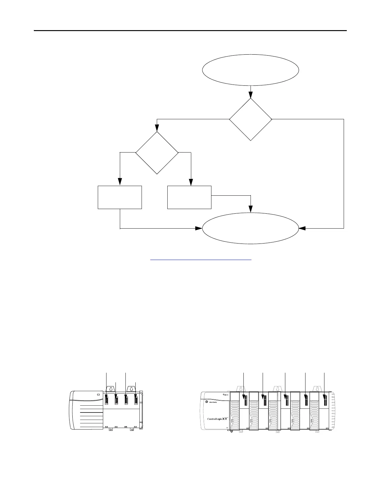
Figure 1 - How the IP Address for the Module is Set
See Set the Network IP Address on page 45 to view all steps for setting the IP
address.
Determine Module Slot
Location
Install the communication module in any slot in a ControlLogix® or
ControlLogix-XT™ chassis. You can install multiple communication modules in
the same chassis.
This example shows the chassis slot numbering in a 4-slot ControlLogix chassis
and a 5-slot ControlLogix-XT™ chassis. Slot 0 is the first slot and is always the
leftmost slot in the chassis.
Module Powerup
Module has an IP
address.
Switches set
from
001…254?
YesNo
Is DHCP or
BOOTP
enabled?
YesNo
Module requests
address from DHCP/
BOOTP server.
Module uses IP address
stored in nonvolatile
memory.
20806
Slot 2Slot 0
Slot 1 Slot 3
ControlLogix Chassis ControlLogix-XT Chassis
31896
Slot 0 Slot 4Slot 1 Slot 2 Slot 3
 Loading...


