40 Rockwell Automation Publication ENET-IN002H-EN-P - August 2017
Chapter 3 Install a 1769 EtherNet/IP Adapter
System Assembly
The adapter can be attached to adjacent 1769 modules before or after mounting.
For mounting instructions, see Mount the Adapter with Screws on page 41
, or
Mount on a DIN Rail on page 42
.
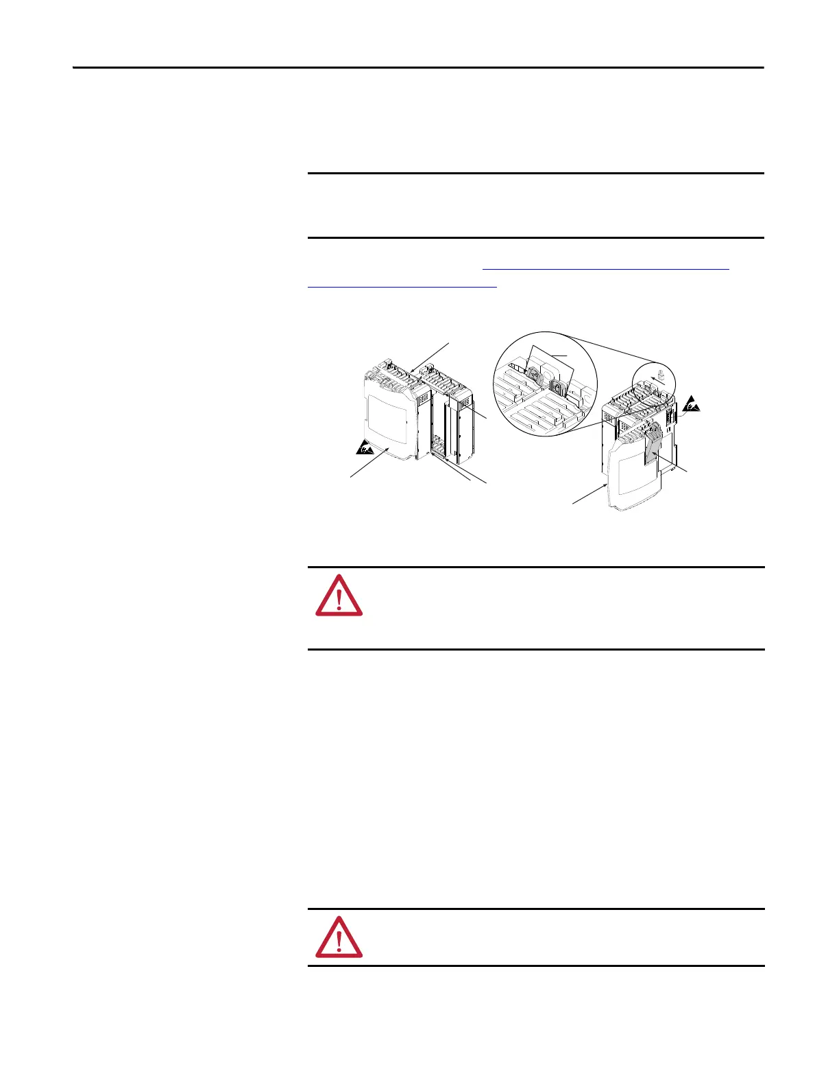
Follow these steps to assemble the Compact I/O™ system.
1. Disconnect power.
2. Check that the bus lever of the module to the right of the adapter is in the
unlocked (fully right) position.
3. Use the upper and lower tongue-and-groove slots (a) to secure the modules
together.
4. Move the module back along the tongue-and-groove slots until the bus
connectors align with each other.
5. Use your fingers or a small screwdriver to push the bus lever of the module
to the right of the adapter back slightly to clear the positioning tab (b).
6. To allow communication between the adapter and I/O modules, move the
bus lever of the module to the right of the adapter fully to the left (c) until
it clicks. Make sure it is locked firmly into place.
The 1769-AENTR adapter must be used with one of the following Rockwell
Automation® power supply models: 1769-PA2, 1769-PB2, 1769-PA4, or
1769-PB4.
WARNING: If you insert or remove the module while backplane power is on, an
electric arc can occur. An electric arc can cause an explosion in hazardous
location installations.
Be sure that power is removed before proceeding.
ATTENTION: When you attach the adapter, it is important that the bus
connectors are securely locked together to create a proper electrical connection.
 Loading...


