22
Features
Input Configuration
Each pair of alarm inputs can be configured to operate from either a normally open or normally closed
Input Contact.
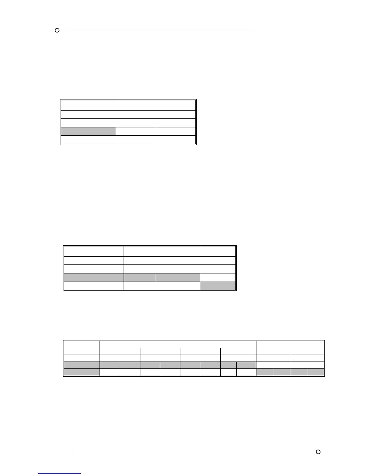
FUNCTION ALARM CARD CHANNEL
1 - 2 3 - 4
SW3.S8 SW5.S8
Normally Open OFF OFF
Normally Closed ON ON
Table 9
Signal Duplicating Relays
The alarm and SPR cards are supplied with an integral repeat relay per channel, which can be
configured to operate as:-
1. Normally de-energised or normally energised
2. Normally open or normally closed contact
3. Input follower or logic follower
De-Energised (Energise On Alarm) or Energised (De-Energised on Alarm)
FUNCTION ALARM CARD CHANNEL SPR CARD
1 - 2 3 - 4 1 - 2
SW4.S2 SW6.S2 SW5.S1
De Energised Relays ON ON ON
Energised Relays OFF OFF OFF
Table 10
Relay Contact Normally Open or Normally Closed (De-Energised Relay State)
Please Note:- LK1 to LK4 refer to the 3 pin headers and 2 way shorting links which are used to select
contact state.

 Loading...