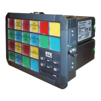
RTK Series UC625 Annunciator
53
Options
Additional options have been developed since the launch of the UC625 Alarm Annunciator but please
note these options must be specified at the time of ordering.
Option 00 Horn Disable On System Test
When the system test pushbutton is pressed on standard UC625 units it simulates a full alarm state
and verifies that the visual and audible circuits are operating correctly. When option 00 is specified the
audible alarms are prevented from operating as a result of the system test pushbutton being pressed.
Please note:- The audible alarms will operate in the normal manner as a result of an alarm input being
abnormal.
Option 01 Lamp Test Instead of Functional Test
Pressing the test pushbuttons on standard UC625 units will simulate a full alarm condition requiring
the operator to also press the mute, ack and reset pushbuttons to clear the alarms after the test has
been activated. In certain applications lamp test is preferred over full functional test and option 01 is
used to signify that pressing the test pushbutton will turn the lamps to steady on while the pushbutton
is being pressed.
Option 02 Ringback Horn Disabled
The standard ISA ringback sequence employed by RTK provides a pulsing horn output to indicate to
the operator that the alarm can be reset. In certain applications the ringback audible is not required
and option 02 permanently disables the audible alarm on any channel returning to normal. Please note
the audible will sound in the normal on alarm activation.
Option 03 ISA R12 Sequence
The standard UC625 provides ISA R sequence but in certain applications the user requires that the
pushbutton functions are interlocked to ensure that the operator steps through the sequence in the
correct order i.e. alarm, silence, acknowledge and reset. Option 03 provides the required pushbutton
interlock, which prevents the pushbuttons operating unless they are pressed in the correct sequence.
Option 04 Response Times
The standard UC625 unit is equipped with DIL switches that allow the user to select each input to
respond to an abnormal state if the contacts have remained in alarm for a minimum time period. Each
alarm can be set to respond in 5, 25, 50 or 100ms on these units. In certain applications the user
requires additional delay with regards to the response time and option 04 provides a minimum setting
of 5ms and a maximum setting of 5 seconds.
Option 05 Lamp / Audible Test
In some applications Customers require the Lamp Test pushbutton to simulate the operation of the
audible alarms whilst the pushbutton is being pressed. Option 05 adds horn test to the lamp test
function.
Multiple Option Codes
To simply the ordering code on the UC625, units that require more than one of the above options use
a suffix letter M and number to indicate which options are fitted.
M1 = Option 00 Fitted
M2 = Options 01 and 02 Fitted
M3 = Options 01, 02, 03 and 04 Fitted
M4 = Options 01, 02, 03, 04 and 05 Fitted

 Loading...