RTK Series UC625 Annunciator
25
Common Alarm Relay
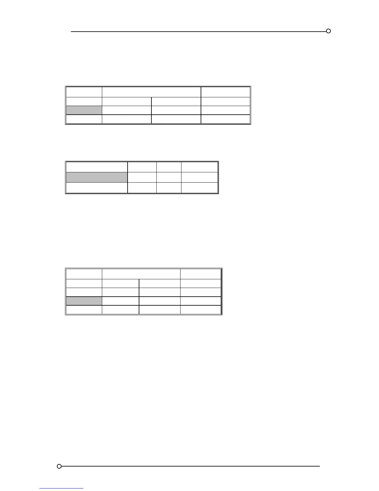
Each unit is equipped with a common alarm relay RL3 to allow a summary alarm contact to be wired to
3
rd
party devices.
FUNCTION ALARM CARD CHANNEL SPR CARD
1 and 2 3 and 4 1 and 2
Enable SW4.S3 = ON SW6.S3 = ON SW5.S2 = ON
Disable SW4.S3 = OFF SW6.S3 = OFF SW5.S2 = OFF
Table 18
The Common Alarm Relay Contact can be set to N/O or N/C as follows:-
CONTACT STATE RELAY LINK SETTING
Normally Open RL3 LK3 N/O
Normally Closed RL3 LK3 N/C
Table 19
Please Note:- LK3 refers to the 3 pin header and 2 way shorting link located on the SPR card used to
select the contact state.
Reflash Option
If a standing alarm is present on the unit and another alarm occurs this option allows the common
alarm relay to change state for 500mS and re-activate hence the term reflash.
FUNCTION ALARM CARD CHANNEL SPR CARD
1 - 2 3 - 4 1 - 2
Reflash SW4.S5 SW6.S5 SW5.S3
Enable ON ON ON
Disable OFF OFF OFF
Table 20

 Loading...