RTK Series UC625 Annunciator
45
DIL Switch Settings SPR Card
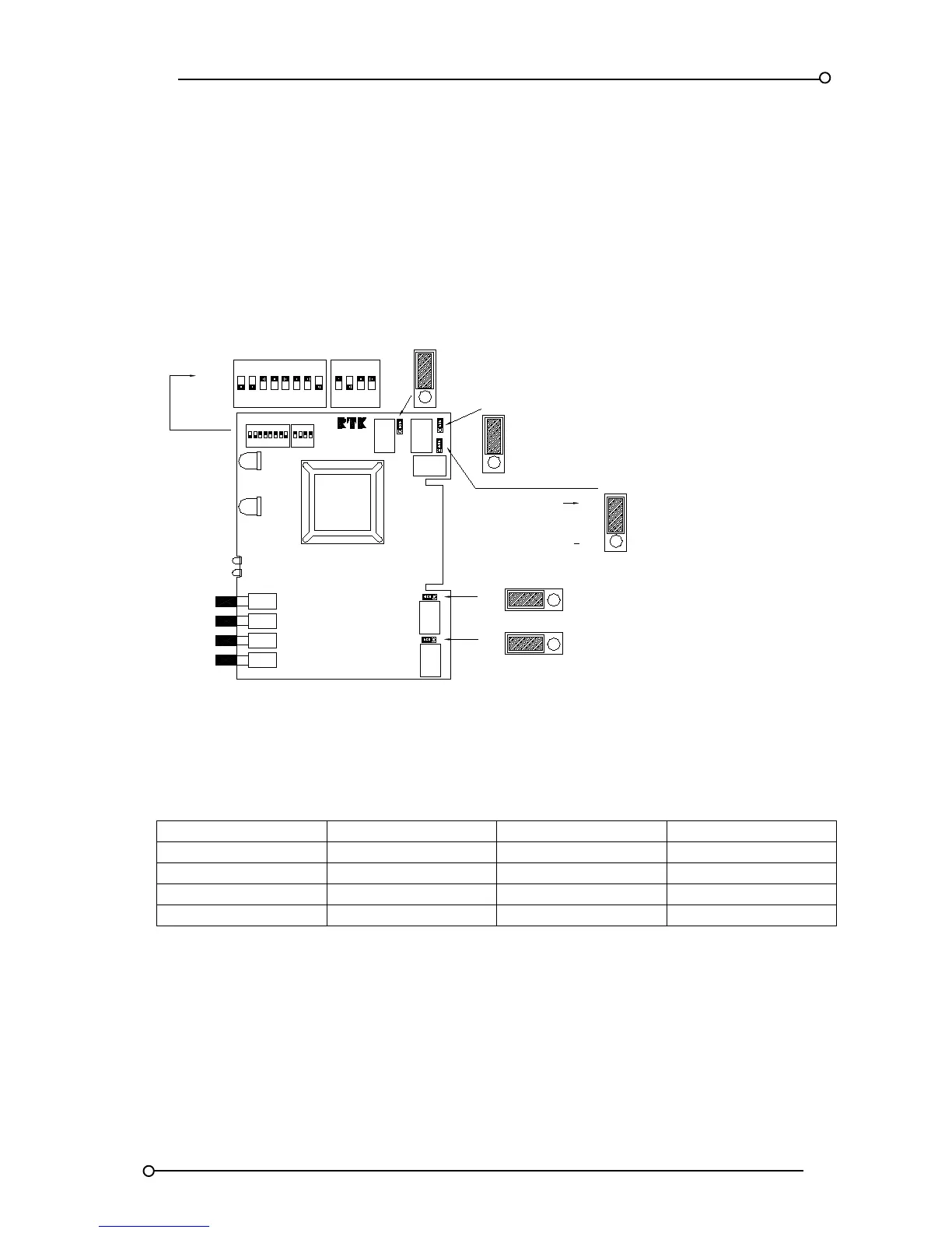
The Supply / Power / Relay, (SPR), card is accessed after removing the front legend plate assembly
by removing the associated screws.
The SPR card is equipped SW5 & SW6 DIL switches, which are used to select various options as
detailed on the following pages.
The SPR card is also equipped with 5 x 3 way header pins and 2 way shorting bars which allow the
user to set the horn, group and power failure relay contacts to Normally Open or Normally Closed as
required.
RL5
ACK
MUTE
RESET
TEST
SW3
SW4
SW2
LED 2
SW1
LED 1
FRONT VIEW
SPR CARD
CB5304POP6
31 2 64 5 87 21 3 4
LED 4
LED 3
8
FAILURE
SUPPLY 2
FAILURE
ALARM
ALARM
SUPPLY 1
ON
3
21 4 5 76
SW 5
AS6520
ASIC
ON
4
21 3
SW 6
SW 5
ON ON
SW 6
NC
HORN RELAY
CONTACT STATE
CONTACT STATE
SUPPLY 2
FAILURE
FAILURE
SUPPLY 1
NC = NORMALLY CLOSED
LK1
LK2
RL1
RL2
NC NO
RL1
NC
RL2
NO
NO
NO = NORMALLY OPEN
LK3
RL4
NC
RL3
NO
NC
ALARM RELAY
CONTACT STATE
GPA COMMON
RL3
CONTACT STATE
HORN RELAY
HNB NON-CRITICAL
LK5
RL5
NO
CONTACT STATE
HNA CRITICAL
RL4
LK4
SPR (Supply, P/B’s and Relays) Card showing DIL switches
Figure 13
The following ASIC versions are used in UC625 models
The optional functions are defined below
M2 = Modified Ringback sequence, disabled ring back audible and lamp test in place of system test.
M3 = ISA R12 Ringback sequence, disabled Ringback horn, lamp test in place of system test and
response time changed to 5mS trip 5S pre-alarm.
M4 = ISA R12 Ringback sequence, disabled ring back audible, lamp test in place of system test,
response time changed to 5mS trip and 5S pre-alarm and combined Lamp / Audible Test
pushbutton function.

 Loading...