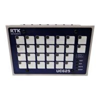
RTK Series UC625 Annunciator
33
Signal Supply
The standard UC625 generates an internal redundant +24VDC for use as the signal supply voltage.
The signal supply voltage is protected by fuse F1 located in the top left hand corner on the rear of the
enclosure and internally linked to all of the “C” terminals of the UC625 for distribution to the associated
signal input contact
.
Signal Supply Monitor Relay
On systems supplied after January 1
st
2008 a field contact supply monitor relay has been
added to provide remote indication of loss of the field contact voltage. The monitor relay
output contact is available on the rear of the unit in terminal row YA terminals FC.
Signal Supply Options
As an option, which must be specified at the time of order, the UC625 can be supplied suitable for use
with direct powered inputs using 48VAC/DC, 110VAC/DC or 250VAC/DC. Please note:- 48VAC/DC,
110VAC/DC and 250VAC/DC signal supply versions use external voltages derived by others from
outside the annunciator.
Full redundancy of operation is therefore dependent on the signal supply voltage being
available if either primary or secondary supply inputs are present.
Earthing
All series UC625 alarm annunciators are fitted with a separate earth stud, which is located on the left
hand side of the enclosure when viewed from the rear. Warning:- To ensure the final installation meets
all relevant safety standards and EMC directives this earth must be connected
Remote Pushbutton Connections
Standard units are supplied with customer terminals which allow connection of remote pushbuttons
which can be set via on board DIL switches to operate in one of two ways as described below.
Option 1
In sub-station applications it is common for a number of annunciators to be wired to one common set
of Test, Acknowledge and Reset pushbuttons which only control the power failure alarms fitted within
individual annunciators
.
Option 2
In other applications both alarms and power failure alarms are to be linked to a common set of Test,
Acknowledge and Reset pushbuttons.
FUNCTION CARD CHANNELS SWITCH SETTING
Enable Option 1 SPR ALL SW5.S7 OFF
Enable Option 2 SPR ALL SW5.S7 ON
Table 25
In either case remote pushbuttons should be momentary type with normally open contact. Switches of
almost any type can be used and should be wired as shown in the following diagram.

 Loading...