54
Trouble Shooting Guide
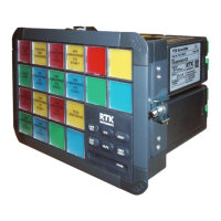
The following section is issued as a guide to aid fault finding on the UC625 alarm annunciator.
Units are shipped from the factory with the default settings highlighted in each section within this
manual unless otherwise advised at the time of order. As a number of features can be enabled or
disabled by the user using the DIL switches located on the alarm and SPR modules it is
recommended that a note is made of any switch settings prior to fault finding.
Symptom Probable Cause
The green LED associated
with supply 1 is not lit and
the power failure alarm is
Measure the voltage on the power input terminals marked supply 1
located on the rear of the unit and verify that the level matches the
requirement and is connected in the polarity indicated.
with supply 2 is not lit and
the power failure alarm is
Measure the voltage on the power input terminals marked supply 2
located on the rear of the unit and verify that the level matches the
requirement and is connected in the polarity indicated.
When the signal input
contact closes or opens no
alarm occurs on the
annunciator
Check that the signal supply fuse F1 rated @ 125mA, located in the top
right hand corner when viewed from the rear of the unit, is in working
order and check that the corresponding signal supply voltage is present
on the customer terminals on the rear of the unit which can be
measured between terminals OVC and any of the terminals marked C
(Common) located at the top of each row of signal input terminals.
Caution:- Although 24VDC is the standard signal supply voltage options
exist for 48VAC/DC, 110VAC/DC, 250VAC/DC.
Although the field contacts
are known to be in the non
alarm condition the alarms
remain in the on state and
cannot be reset
If alarms are set to operate from normally closed contacts and the signal
supply fuse blows all alarms will operate as though an alarm has
occurred and after the ack and reset pushbuttons have been pressed
the alarms will remain in steady on state and cannot be reset until the
supply is re-instated.
Check that the signal supply fuse F1 (rated at 125mA) has not blown.
Fuse F1 is located in the top right hand corner of the unit when viewed
from the rear.
Check that the Inputs have been correctly set to operate from either a
normally open (N.O.) or normally closed (N.C.) and they have not been
accidentally inverted.
The following switch settings are used to set the input type
Channel 1 & 2
SW3 Position 8 OFF = N.O.
SW3 Position 8 ON = N.C.
Channel 3 & 4
SW5 Position 8 OFF = N.O.
SW5 Position 8 ON = N.C.

 Loading...